Basics of CLI on Cisco
Privileged EXEC Mode
Provides complete access to view device configuration, restart the device, etc.
Cannot change the configuration, but can change the time on the device, save configuration files, and more.
1 | Router>enable |
How to Enter Global Configuration Mode
1 | Router>enable |
Enable Password
1 | Router(config)#enable password LINE |
Running-Config / Startup Config
1 | Router#show running-config |
1 | Router#show startup-config |
Saving the Running Configuration
1 | Router#write |
Service password-encryption
- Changes the way passwords are displayed.
- If enabled, current passwords will be encrypted.
- Future passwords will be encrypted.
enable secretswill not be affected
- If you disable
servie password-encryption:- current passwords will not be decrypted
1 | Router# conf t |
Enable Secret Command
1 | Router(config)#enable secret Cisco |
- Uses MD5 encryption, but a little tougher to crack than regular password encryption.
enable secretdoes not require thepassword-encryptioncommand to be enabled.
Canceling Commands
- Use
no1
Router(config)#no service password-encryption
Overview
Router>= user EXEC modeRouter#= privileged EXEC modeRouter(config)#= global configuration mode
1 | Router>enable |
Ethernet Lan Switching (Part 1)
Quick OSI Model Review
Data Link
- Provides node to node connectivity and data transfer (PC to switch, switch to router, router to router)
- Defines how data is formatted for transmission over a physical medium (e.g., copper UTP cable)
- Detects and possibly correct Physical layer errors
- Uses Layer 2 addressing, separate from layer 3 addressing
- Switches operate a layer 2
Local Area Networks (LANs)
- Local networks are separated by routers, not switches.
The focus will be how switches receive and forward specifically ethernet “frames”. [so layer 2…]
Ethernet Frame
Ethernet header / Packet / Eth. Trailer
In the ethernet header:
- Preamble - SFD - Destination - Source - Type
- Preamble and SFD (start frame delimiter): used for synchronization
- Destination: layer 2 address
- Source: layer 2 address
- Type: indicates the layer 3 protocol (typically always IPv4 or IPv6)
- However, it can also be a length field.
- Preamble - SFD - Destination - Source - Type
In the ethernet trailer:
- Only one part: FCS (Frame Check Sequence): used by the receiving device to detect for errors
Preamble and SFD (Start Frame Delimiter)
- Preamble is 7 bytes (56 bits).
- Alternating 1’s and 0’s (10101010 * 7)
- Allows devices to synchronize their receiver’s clock
- Alternating 1’s and 0’s (10101010 * 7)
- SFD’s length is 1 byte (8 bits)
- 10101011 (notice it ends in a 1)
- Marks the end of the preamble and the beginning of the rest of the frame.
Destination and Source Field
- Indicate the devices sending and receiving the frame.
- Consists of the destination and source ‘MAC’ address
- MAC = Media Access Control = 6 byte (48-bit) address of the physical device
Type OR Length Field
- 2 byte (16 bits)
- A value is 1500 or LESS in this field, indicates the LENGTH of the encapsulated packet in bytes
- A value of 1536 or GREATER in this field, indicates the TYPE of the encapsulated packet (usually IPv4 or IPv6)
- IPv4 = 0x0800 (2048 in decimal)
- IPv6 = 0x86DD (34525 in decimal)
HEADER | TRAILER
[Preamble (7) - SFD (1) - Destination (6) - Source (6) - Type (2)] [FCS (4)]
Ethernet Trailer: FCS (Frame Check Sequence)
- 4 bytes (32 bits)
- Detects corrupted data by running a ‘CRC’ algorithm over the received data
- CRC = ‘Cyclic Redundancy Check’
Total Size of Ethernet Frame
- 26 bytes. Do you know the sizes individually?
MAC Address
6 byte (48 - bit) physical address assigned to the device
A.K.A ‘Burned-In Address’ (BIA)
MAC addresses are globally unique…
The first 3 bytes are the OUI (Organizationally Unique Identifier) - which are assigned to a company
Last 3 bytes: are unique to the device itself.
Written as 12 hexadecimal characters.
Dynamically learned MAC address (switches keep track of MAC addresses and fills dynamically as network traffic flows)
Unicast frames: a frame destined for a single target
Unknown Unicast Frame:
- If a switch does not know where the destination is; the only option is to FLOOD the frame, which means it copies the frame and sends it out to every other system/device (except for where the switch received the frame).
- A switch will only know where the receiver is if the destination responds back. Otherwise, the switch will continue to FLOOD.
- If a switch does not know where the destination is; the only option is to FLOOD the frame, which means it copies the frame and sends it out to every other system/device (except for where the switch received the frame).
For CISCO, dynamic MAC addresses are removed after 5 minutes of inactivity.
Other
- Recall FO/1, where F stands for “Fast ethernet”
Questions
- Which field of an Ethernet frame provides receiver clock synchronization?
- Preamble.
- How long is the physical address of a network device?
- 48 bits (6 bytes)
- What is the OUI of this MAC Address? E8BA.7011.2874
- E8BA.70 - OUI is the first HALF.
- Which field of an Ethernet frame does a switch use to populate its MAC address table?
- Source address.
Ethernet Lan Switching (Part 2)
Ethernet Frames - Cont. - Preamble and SFD does “not” count.
- Preamble and SFD is usually NOT considered part of the Ethernet header.
- Therefore, the size of the Ethernet header is “technically” 18 bytes.
- [Preamble (7) - SFD (1)] || [Destination (6) - Source (6) - Type (2)] + [SFD (4)]
- The minimum size of an Ethernet frame is 64 bytes.
- 64 bytes - 18 bytes (header + trailer size) = 46 bytes (if 802.1q (4) tags are not used)
- Therefore, the minimum payload (packet) size is 46 bytes. If the payload is less than 46 bytes, padding bytes are added. Padding bytes consists of just 0’s.
Ethernet LAN Switching
- First half of the MAC address indicates the organization/company.
- When you send data, it includes more than just a source and destination MAC address. It also includes an IP packet, which includes SRC IP and DST IP.
- When you send data, the sender doesn’t necessarily know the receiver’s MAC address. Remember, these switches are layer 2 devices. They don’t operate at layer 3.
- So, how does it learn PC 3’s MAC address?
ARP
- ARP stands for ‘Address Resolution Protocol’
- ARP is used to discover the Layer 2 address (MAC address) of a known Layer 3 address (IP address).
- Consists of two messages: ARP Request and ARP Reply.
- ARP Request is send as a broadcast = sent to all hosts on the network
- ARP Reply is a unicast which is only send to one host.
ARP Request
- Before PC1 sends something to PC3, it must send an ARP Request Frame.
- Notice the ‘FFFF.FFFF.FFFF’, which is known as a broadcast frame.
- It is similar to an unknown unicast frame.
- A broadcast frame is dropped when the destination IP address does not match.

- Once the ARP Request reaches its intended sender (by matching IP addresses), an ARP reply is sent back.

- Finally, when the ARP reply is received by the original sender (PC 1), it is added to the ARP table.
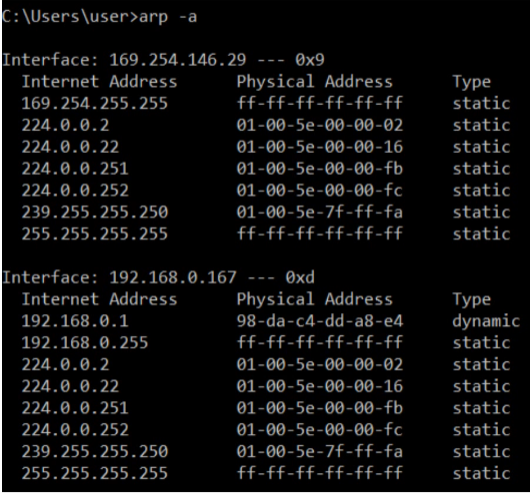
[CMD] arp - a
- Use
arp -ato view the ARP table. - Internet Address = IP Address (Layer 3 address)
- Physical Address = MAC address (Layer 2 address)
- Type static = default entry
- Type dynamic = learned via ARP
Ping
- Network utility to test reachability
- Measures Round-Trip-Time (RTT)
- Uses two messages (like ARP): ICMP Echo Request and ICMP Echo Reply
- However, unlike ARP, it is sent to a specific host, so it must know the destination of the MAC address, which is why ARP must be used first.
What is the arp command in Linux, Mac, Windows IOS? What about CISCO?
- Windows/Mac/Linux all use
arp - Cisco switches use
show arpfrom previlged EXEC mode
This is a ping request on a CISCO switch. What is a likely reason the first ping failed?

- PC1 likely did not know the destination MAC address. So it had to use ARP first.
Take a look at the ARP table after the ping.
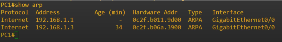
Notice the protocol ARP.
The ARP request is asking “Who has 192.161.1.3” and to ‘Tell 192.168.1.1’.
Followed by an ARP reply on frame 2.

Also note in frame 4 and frame 5 have reversed source and destination.

In short, if device A wants to send traffic to device B on the SAME NETWORK, device A must use ARP. Then it can send traffic to device B.
MAC Address Table on Cisco and Commands
#show mac address-table

- Aging: if a Cisco switch does not receive any traffic from that MAC address for 5 minutes, it’ll delete.
- Another way
clear mac address-table dynamic - If you want to delete a specific mac address:
clear mac address-table dynamic address MAC-ADDRESS - You can also do it via interface:
clear mac address-table dynamic interface INTERFACE-ID
Ethernet Frame (Cont.) What if we send a ping with a payload of size 36?
#ping 192.168.1.3 size 36
- Recall that the minimum payload size of an ethernet frame (not accounting for the preamble and SFD) is 46 bytes.
- If we send a size 36 byte payload, how many 0’s will there be in the padding?
- Each hexadecimal 0 = 4 bits ((recall hexadecimal is 16, so 2^4, takes 4 bits to represent one hexadecimal number))
- So, 00 = 8 bits = 1 byte
- If you count the 0’s, there should be 20 bits (10 bytes).
What is the ARP ethernet Type?
- ARP: 0x0806
- IPv4: 0x86DD
- IPv6: 0x0800 (?)
Conclusion
- Ethernet frame payload minimum size
- ARP (Address Resolution Protocol): ARP Request/Reply
- ARP Table (in CISCO)
- Ping (ICMP Echo Request/Reply)
- MAC Address (CISCO clear MAC addresses all/via MAC address/via INTERFACE ID)
Question 1
You send a 36-byte ping to another computer and perform a packet capture to analyze the network traffic. You notice a long series of bytes of 00000000 at the end of the Ethernet payload. How can you explain these zeros?
- Padding bytes.
- The minimum payload size is 46 bytes.
Question 2
Which of these messages is sent to all hosts on the local network?
a. ARP Request - Answer – learns a layer 2 address of the host, which if not known, needs to be broadcast to all host on the network.
b. ARP Reply : unicast message –
c. ICMP echo request: – also a unicast message, requires
d. ICMP echo reply – also a unicast reply
Question 3
Which fields are present in the output of the show mac address-table command on a Cisco switch?
C) VLAN, MAC Address, Type, Ports
Question 4:
Which type of frames does a switch send out of all interfaces, except one frame was received on?
- Broadcast AND unknown unicast.
- Broadcast frames have a destination address of FFFF.FFFF.FFFF and are sent to all hosts on the local network.
- Unknown unicast frames are destined for a single host. However, the switch does not have an entry for the destination in its MAC address table so it must flood the frame.
Question 5:
Which command is used on a Cisco switch to clear all dynamic MAC addresses on a specific interface from the MAC address table?
clear mac address-table dynamic interface INTERFACE-ID
IPv4 Addressing (Part 1)
Recall Layer 3: Network Layer
- Provides connectivity between end hosts on different networks (outside of the LAN)
- Provides logical addressing (IP addresses)
- Provides path selection between source and destination.
- Routers operate at Layer 3
Routing
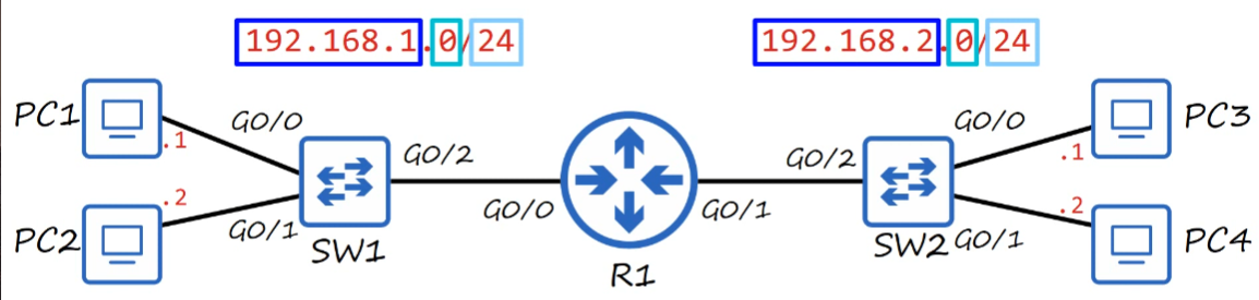
- Recall switches simply expand networks. Therefore, PCs within the same LAN have the same IP addresses within the same network.
What does the IP address indicate?
- The three group 192.168.X indicates network itself.
- Y in 192.168.X.Y represents the PCs/clients/servers.
- The
/24represents the network and which part represents the end-host./24says the first 3 group of the numbers represents the network.
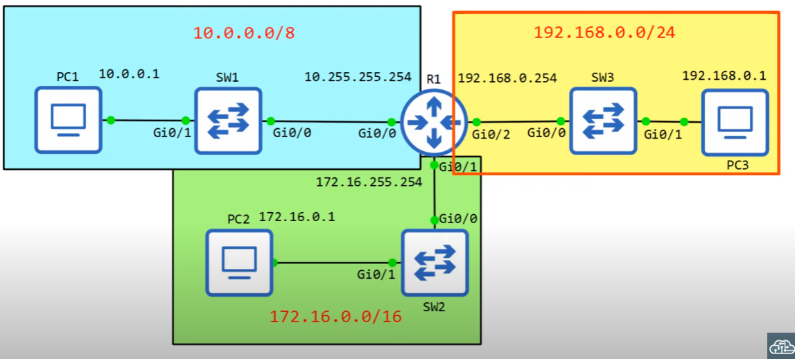
The router in the picture above requires an IP address.
G0/0interface is given 192.168.1.254G0/1interface is given 192.168.2.254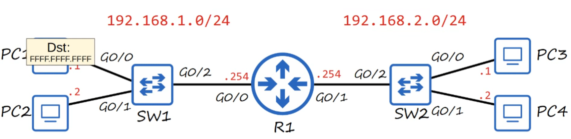
- The broadcast signal is forwarded to 192.168.1.2 and 192.168.1.254.
- Broadcast signals are limited within the local network.
IPv4 Header (Let’s focus on Source and Dest IP address atm)
- IP addresses are 32 bits (4 bytes) in length.
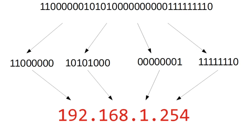
192.168.1.254: A closer look
- Each group of numbers represents 8 bits.
- 192 = 8 bits => 11000000
- 168 = 8 bits => 10101000
- 1 = 8 bits => 00000001
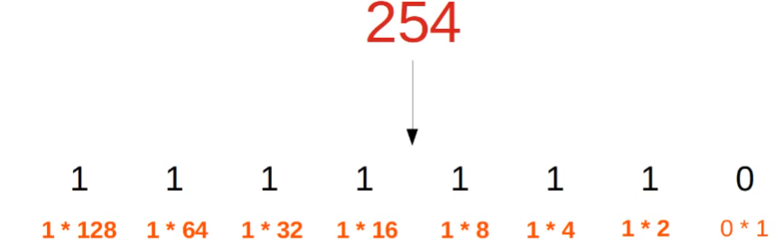
- 254 = 8 bits = 11111110
- Instead of binary, we use dotted decimal.
Recall Decimal, Hexadecimal, and Binary Notation
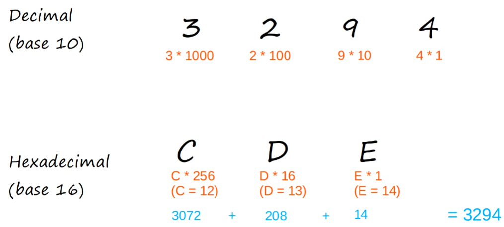
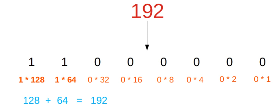
Decimal to Binary…

The range of possible numbers of binary can range from?
0 - 255
IPv4 address is a series of 32 bits
So what is the /24?
- The
/24indicates the first 24 bits represents the network portion, and the remaining 8 represents the host.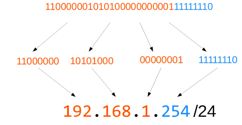
/16 indicates the first half.

/8

IPv4 Address Classes
| Class | First octet | First octet numeric range | ||
|---|---|---|---|---|
| A | 0xxxxxxx | 0-127 | 64+32+16+8+4+2+1 = 127 | Really 0 - 126, not 127. |
| B | 10xxxxxx | 128 - 191 | 128 + 32 + 16 + 8 + 4 + 2 + 1 = 191 | |
| C | 110xxxxx | 192-223 | ||
| D | 1110xxxx | 224-239 | Reserved for multicast (different from unicast and broadcast) | |
| E | 1111xxxx | 240-255 | Reserved for experimental use |
Why is class A range in practice only 0 - 126? Loopback Addresses
- The 127 octet range is reserved for loopback addresses. What does that mean?
- The first octet is always 127.
- Address range 127.0.0.0 - 127.255.255.255
- Used to test the ‘network stack’ (think OSI, TCP/IP model) on the local device.
- If a device sends any network traffic in this range, it’s simply sent back up the network stack (think of when you receive a packet and it’s being de-encapsulated).
- This is demonstrated by the RTT when pinged.
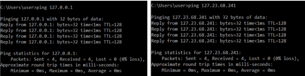
- The first octet is always 127.
Implications of Class A, B, C.
| Class | First octet | First octet numeric range | Prefix Length | ||
|---|---|---|---|---|---|
| A | 0xxxxxxx | 0-127 * really 0 - 126 | /8 | ||
| B | 10xxxxxx | 128 - 191 | /16 | ||
| C | 110xxxxx | 192-223 | /24 |
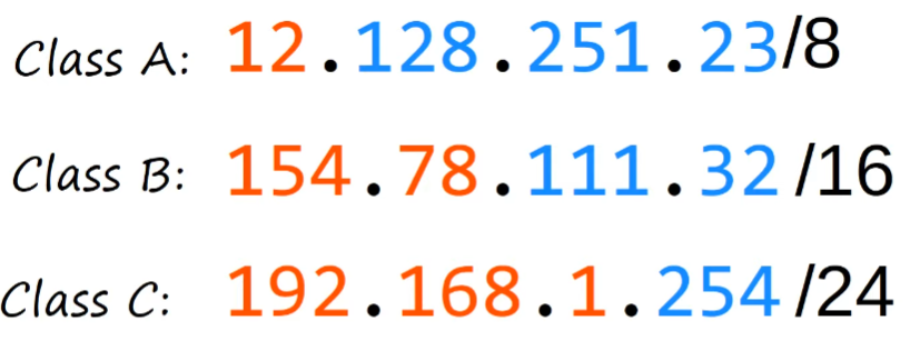
- Class A: Fewer potential networks, there can be many hosts on each network
Class C: there are many possible networks, but there can only be a few hosts.
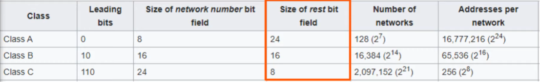
- Indicated by the chart above, class C networks can only have 256 possible hosts.
- However, the first bit is reserved for the network. AND the last address of the network is the broadcast network (the layer 3 address when you want to send traffic to all host
- So really, the host count is 2 LESS. 256 - 2 = 254 in class C
Netmask: “A Newer and Easier Way of Writing the Prefix Length?”
In juniper networks, we use the slash notation.
- Class A: /8
- Class B: /16
- Class C: /24
Cisco networks use an older method: dotted decimal netmask
- Class A: 255.0.0.0 (11111111 00000000 00000000 00000000)
- Class B: 255.255.0.0 (11111111 11111111 00000000 00000000)
- Class C: 255.255.255.0 (11111111 11111111 11111111 00000000)
The network address CANNOT be assigned to the host.
- If the host portion of the address is all 0’s, then it is a network address.
192.168.1.0/24 = network address
192.168.2.0/24 = network address
The first usable host address is 192.168.1.1/24
The last address in the network is the broadcast address.
- If the host portion of the address is all 1’s, then it is the broadcast address.
192.168.1.255/24 (X.X.X.1111111)
The last usable host address is 192.168.1.254/24
In short, we talk about
- Dotted decimal and binary
- Network portion / host portion of IPv4
- IPv4 address classes
- Prefix lengths / netmasks (Cisco)
- Network address / broadcast address
Question 0
If we sent a ping to 192.168.1.255, what would be the destination MAC address?
- Given that 255 is the broadcast address, the destination MAC address should be FFFF.FFFF.FFFF
IPv4 Addressing (Part 2)
Overview
- IPv4 Address Classes (review and clarification)
- Finding the: maximum number of hosts, network address, broadcast addsress, firstusable address, last usable address (on a particular network)
- Configuring IP addresses on Cisco Devices
| Class | First octet | First octet numeric range | ||
|---|---|---|---|---|
| A | 0xxxxxxx | 0-127 | Usable range is 1 - 126 | |
| B | 10xxxxxx | 128 - 191 | ||
| C | 110xxxxx | 192-223 | ||
| D | 1110xxxx | 224-239 | Reserved for multicast (different from unicast and broadcast) | |
| E | 1111xxxx | 240-255 | Reserved for experimental use |
Calculate Maximum Hosts Per Network
Class C
192.168.1.0/24 -> 192.168.1.255/24
- Host portion = 8 bits = 2^8 = 256
- 192.168.1.0/24 = network address
- 192.168.1.255/24 = broadcast address
- 256 - 2 = 254
Class B
172.16.0.0/16 -> 172.16.255.255/16
- Host portion = 16 bits = 2^16 = 65,536
- 172.16.0.0/16 = network address
- 172.16.255.255/16 = broadcast address
- Maximum hosts per network = 65,534
Class A
10.0.0.0/8 -> 10.255.255.255/8
- Host portion = 24 = 2^24 = 16,777,216
- 10.0.0.0/8 = network address
- 10.255.255.255/8 = broadcast address
- Maximum hosts per network = 16,777,214
Maximum host per network = 2^n - 2
First/Last Usable Address
Class C
192.168.1.0/24 -> 192.168.1.255/24
- First usable address = 192.168.1.1/24
- Last usable address = 192.168.1.254/24
Class B
172.16.0.0/16 -> 172.16.255.255/16
- First usable address = 172.16.0.1/16
- Last usable address = 172.16.255.254/16
Class A
10.0.0.0/8 -> 10.255.255.255/8
- First usable address = 10.0.0.1/8
- Last usable address = 10.255.255.254/8
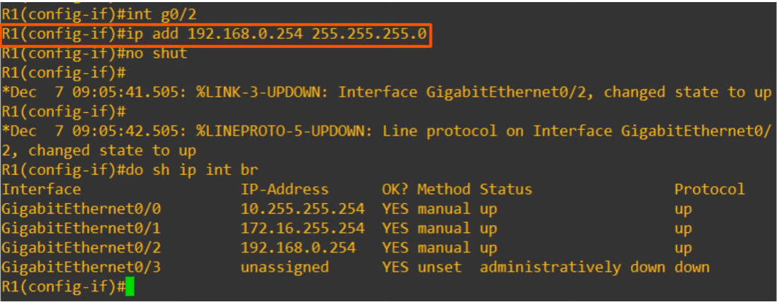
Configuring Cisco Router with IP Address
Create the following configuration using Cisco.
Log in to CLI of R1
1 | R1>en |
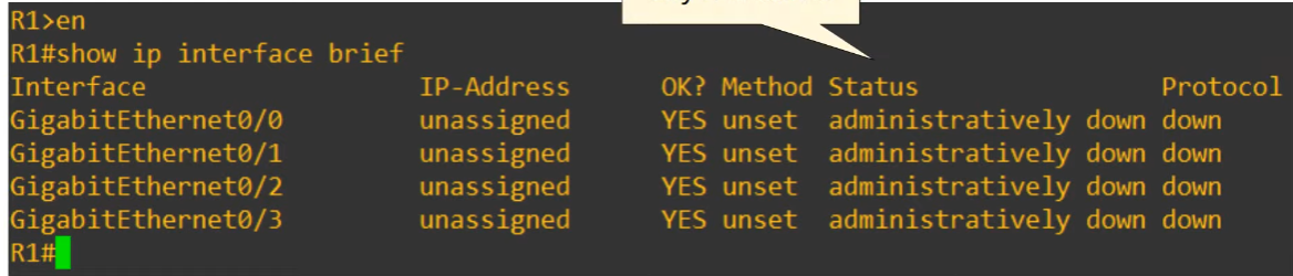
- Status: refers to Layer 1 status
- Protocol: Layer 2 status
Now to edit the interface – do the following in global configuration mode
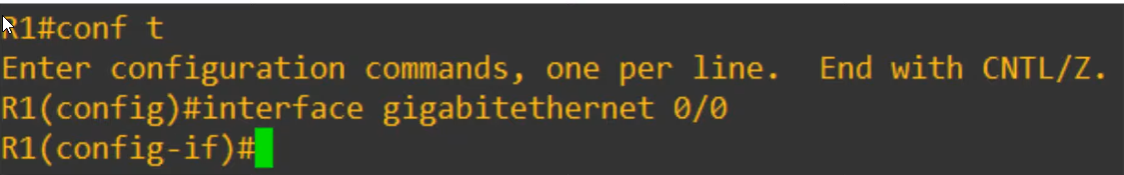
Now that we are inside the ethernet config, we can assign an IP address to that specific interface.
Notice that we must type out the Cisco netmask (and not the slash notation) for this class A network.
Also recall that Cisco router interfaces have the “shutdown command” applied to them by default. We disabled that command with
no shutdown.
dois used to execute a privileged EXEC command from config mode.do sh ip int br=do show ip interface brief
The interface configuration is a success.
Let’s do the config for the Gi0/1 interface next.
We want the network address is 172.16.255.254 for the router…(?)
The network is 172.16.0.0/16. What will the subnet mask be?
We can directly switch from one interface to another. Notice how we left off at the previous int g0/0. Now we are in
int g0/1
Let’s configure R1 Gi0/2 interface to have an ip address of 192.168.0.254.
- Given the prefix is /24. The subnet mask should be 255.255.255.0.
Other show commands
#show interface: will show way too many interfaces. so it’s important to be specific.- specify the interface.
- GigabitEthernet0/0 is up, line protocol is up.
- GigabitEthernet0/0 is up : layer 1 is working.
- line protocol is up : refers to layer 2 status of the interface.
#show interfaces description
To configure a interface description: description LINE

Switch Interfaces - 9
Contents
- Interface speed and duplex
- Speed and duplex auto-negotiation
- Interface status
- Interface counters & errors
- Switch interfaces:
- ASR 1000-X Router vs Catalyst 9200 Switch
- Routers has 8 SFP interfaces for fiber optic, and a few RJ45 for console ports.
- Switch has 4 SFP interfaces, and 48 RJ45 interfaces.
- ASR 1000-X Router vs Catalyst 9200 Switch
Network Topology

show ip interface brief
- Unlike routers, switches do NOT have the
shutdowncommand applied. So they’ll usually be in the up-up state with no configuration required.- IP addresses in a switch is unassigned because these are layer 2 switch ports. They don’t need an IP address.
- (In a later part, multi-layer switching do require IP addresses)
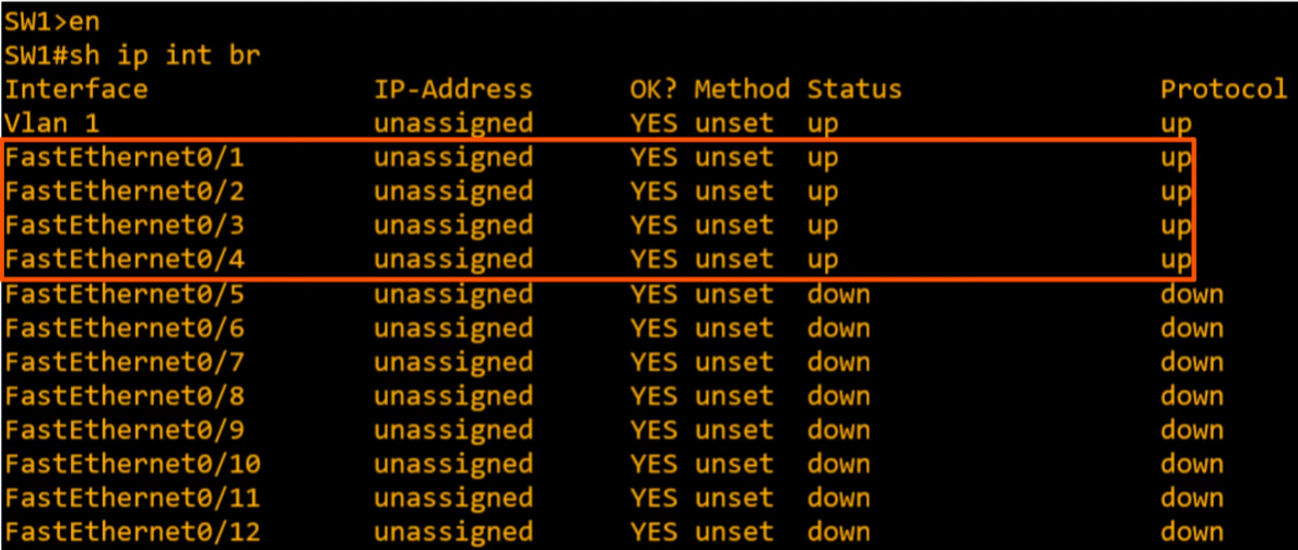
- Keep in mind, here that Router’s “administratively down” is NOT the same as Switch’s down-down. Here, down-down simply means they are not connected to a device.
show interfaces status
- Name = same as description
- Status = different from the Status in above.
- Duplex; = a-full (auto full)
- Speed; = a-100 (auto-100) because Fast Ethernet cables operate at 100Mbps. However, they can also operate at 10 Mbps when necessary depending on the device.
- Type; = 10/100BaseTX (RJ45)

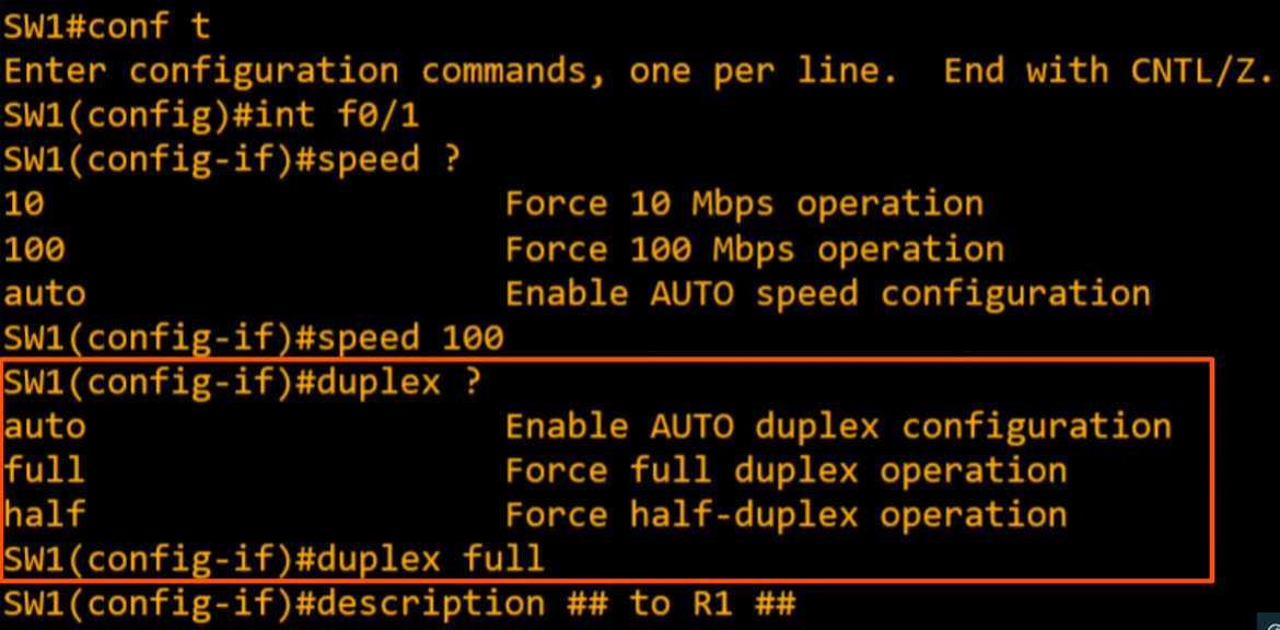
Configure the interface speed and duplex.
- Typically auto-negotiation works well enough on its own, but let’s explore options.
 - After configured…
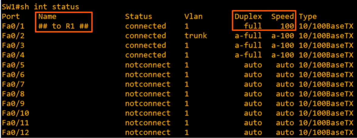
How to disable remaining interfaces we don’t use? interface range
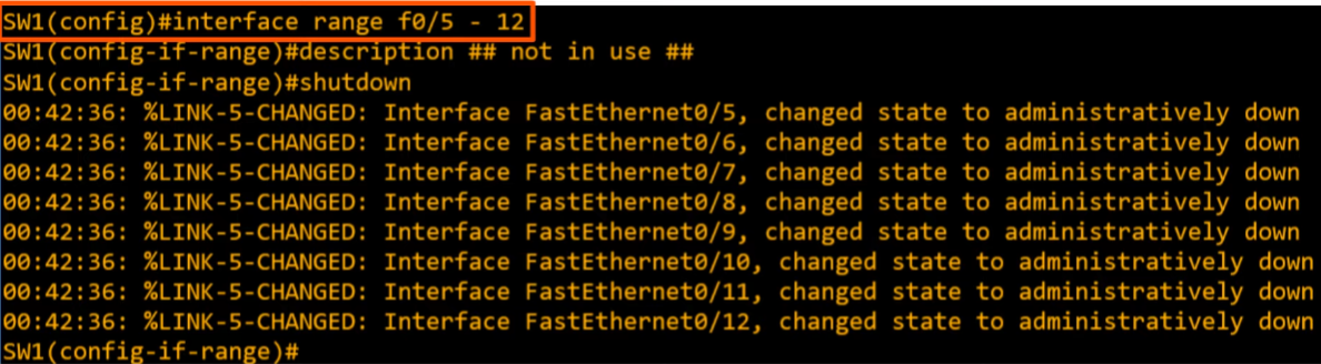
- Here is another way to select interfaces.

Full and Half-Duplex
- Half duplex: device cannot receive and send data at the same time.
- Full duplex: sends and receives simultaneously.
Purpose of half-duplex? Hubs are layer 1 devices; repeaters.
- Back in the day, a “hub” was a half-duplex. There was an issue with collision, and the entire network connected to a half duplex hub was considered part of a “collision domain”.
- CSMA/CD : Carrier Sense Multiple Access with Collison Detection
- Before sending frames, devices ‘listen’ to the collision domain until they detect that other devices are not sending frames.
- If a collision does occur, the device sends a jamming signal to inform the other devices that a collision happened.
- Each device will wait a random period of time before sending frames again.
- Repeat.
Speed/Duplex Autonegotiation
Default settings of interfaces that have varying speeds run at “speed auto” and “duplex auto”.
Ethernet (E) = 10 Mbps
Fast Ethernet (F) 10/100 Mbps
Gigabit (G) = 10/100/1000 Mbps

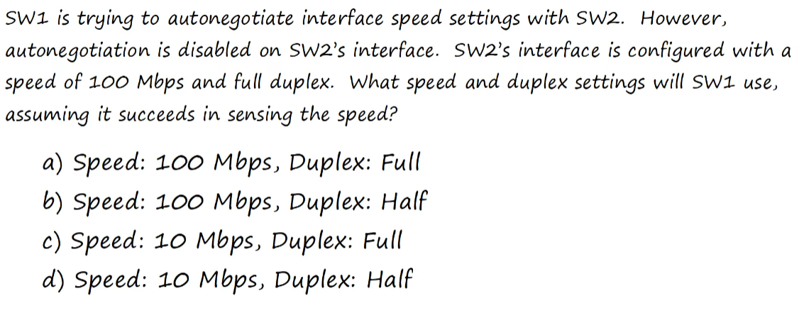
What if auto-negotiation is disabled on the device connected to the switch?
SPEED
- The switch will try to sense the speed, but the default to the lowest supported speed.
DUPLEX
- The switch will use half duplex if speed is 10 or 100 Mbps.
- Else, the switch will use full duplex for 1000 Mbps or greater.
Why does duplex mismatch occur?
Assuming auto-negotiation is disabled here.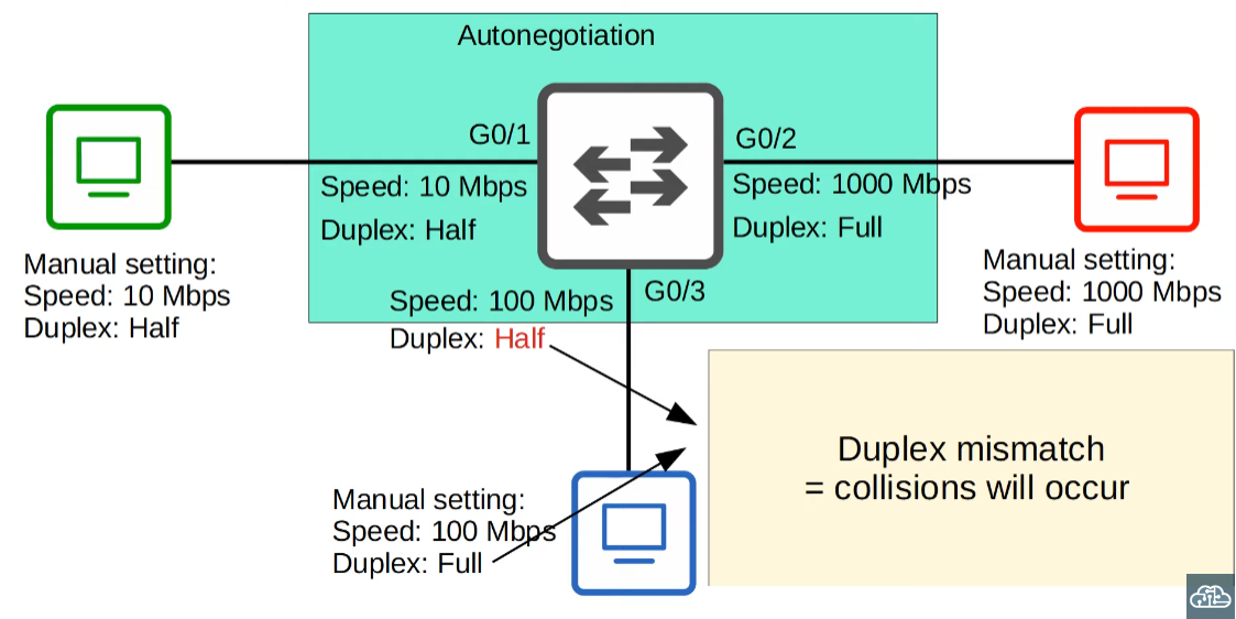
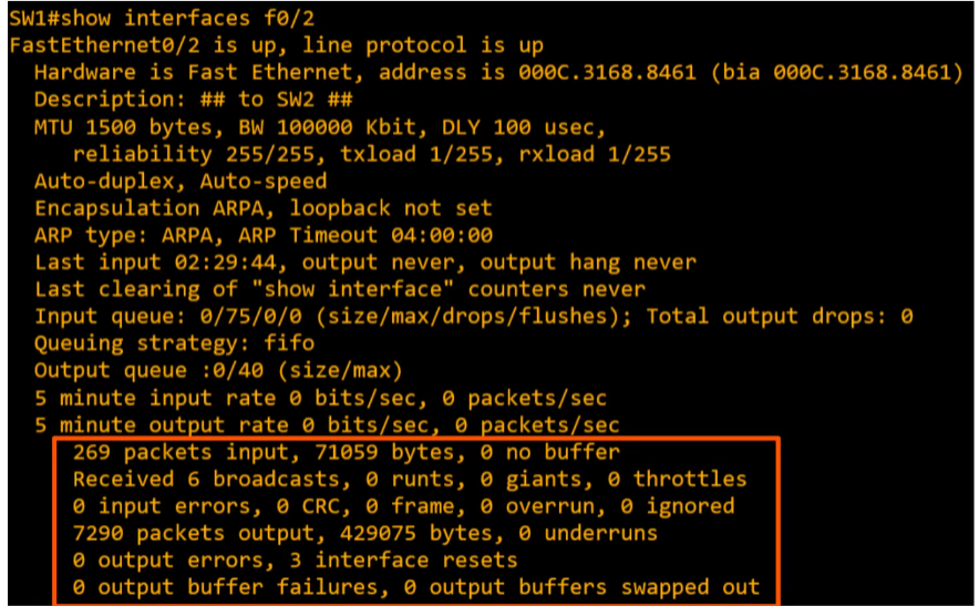
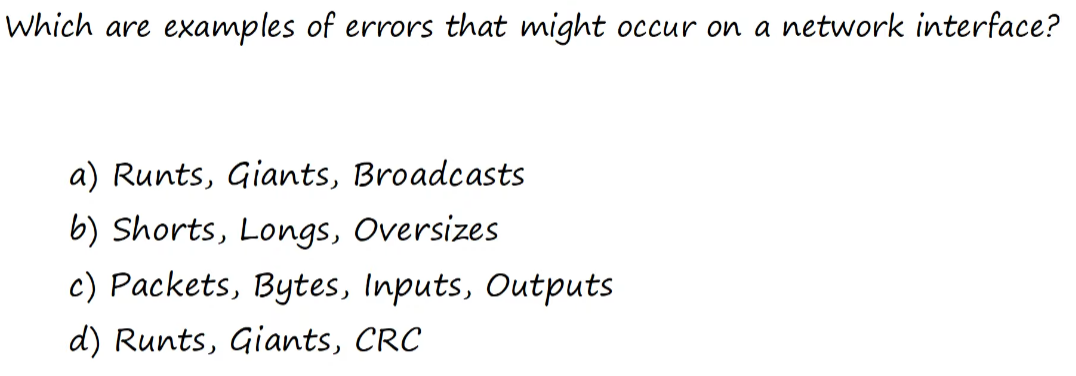
Interface Errors
- Runts: frames that are smaller than the minimum frame size (64 bytes)
- Giants: Frames that are larger than the maximum frame size (1518 bytes)
- CRC: Frames that failed the CRC check (in the Ethernet FCS trailer)
- Checks errors and counts them.
- Frames: Frames that have an incorrect format (due to an error)
- Input errors: Total of various counters, such as the above four.
- Output errors: Frames that a switch tried to send, but failed due to an error
Questions 1
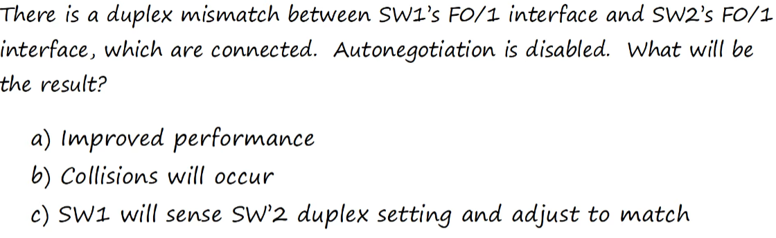
B. Collision mismatch due to auto-negotiation being disabled.
Questions 2
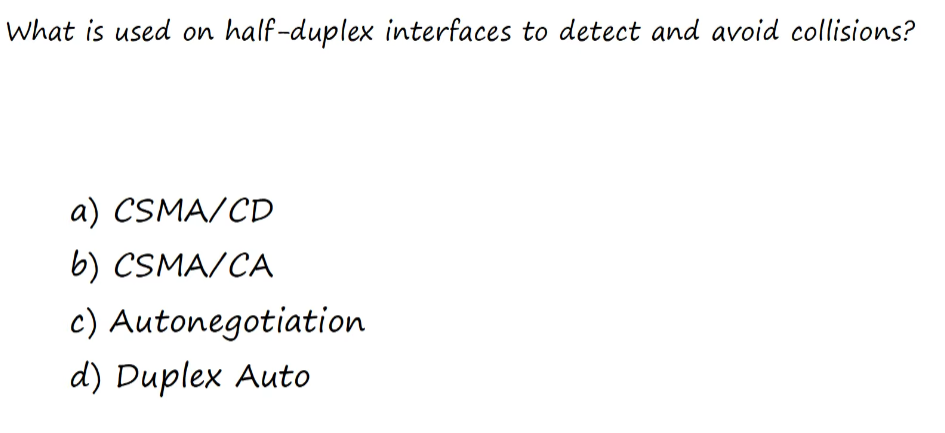
A. CSMA/CD - recall from above for the steps.
Devices using half-duplex listen to activity, send data when other devices aren’t sending. And describes how devices will react when collision does occur.
CMSA/CA - is something different.
Questions 3
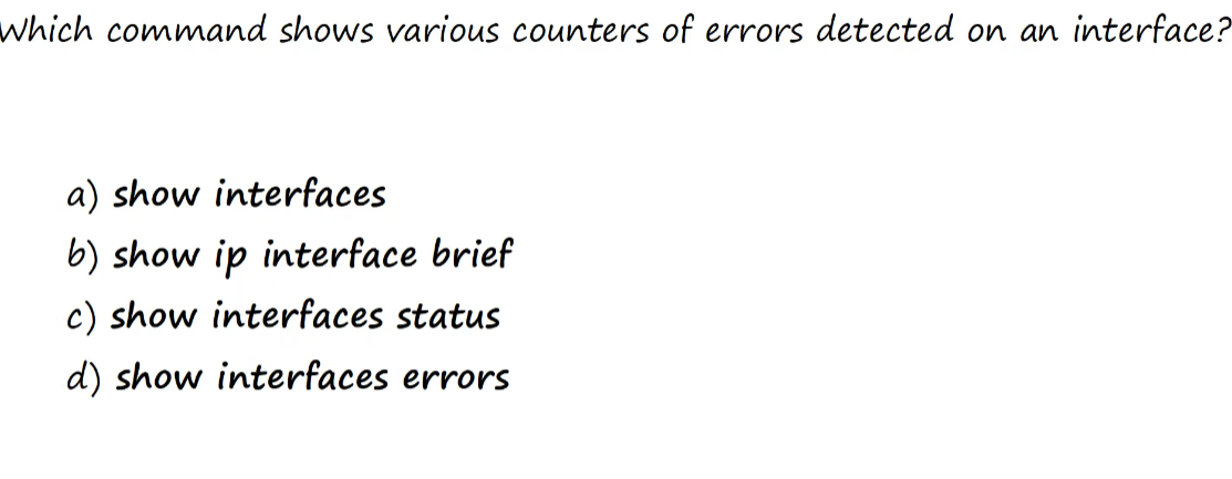
- A. show interfaces
Questions 4
D.
Questions 5
B.
IPv4 Header - 10
IPv4 is used as a Layer 3.
Overview
- IPv4 packet structure (header used to encapsulate TCP or UDP)
- Fields of IPv4 Header
OSI Model - PDUs
Protocol Data Units (PDU)
Data // Data
Data/L4 Header // Segment
Lata/L4 Header/L3 Header // Packet
L2 Trailer/Data/L4 Header/L3 Header/L2 Header // Frame
IPv4 Header focuses on L3 Header.
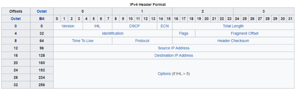
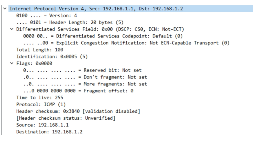
IPv4 Header

Version: 4 bits; identifies version of IP used (IPv4 (0100) or IPv6 (0110))
IHL (Internet Header Length): 4 bits;
- Minimum of 5?
- Maximum of 15?
DSCP (Differentiated Services Code Point): 6 bits
- Used for QoS (Quality of Service)
- QoS is used to prioritize delay-sensitive data (streaming voice, video, etc)
- Used for QoS (Quality of Service)
ECN (Explicit Congestion Notification): 2 bits;
- Provides end-to-end notification of network congestion WITHOUT dropping packets.
- (Normally, when congestion occurs, packets are dropped).
- This is an optional field that requires both endpoints as well as the underlying network to support it.
- Provides end-to-end notification of network congestion WITHOUT dropping packets.
Total Length: 16 bytes;
- Indicates the total length of the packet (L3 header + L4 segment) (and the data(?))
- This is different from the ‘IHL’ header, which only indicates the length of the IPv4 Header itself.
- Measured in 1 byte increments (not like 4-byte increments like IHL)
- Minimum value of 20 (=IPv4 header with no encapsulated data)
- Maximum value of 65,535 (maximum of 16-bit)
- 1111111111111111
Identification Field: Length 16 bits
- If a packet is fragmented due to being too large, this field is used to identify which packet the fragment belongs to.
- All of the same packet will have their own IPv4 header with the same value in this field.
- Packets are fragmented if larger than the MTU (Maximum Transmission Unit)
- MTU is usually 1500 bytes
- Remember the maximum size of Ethernet Frame?
- Maximum payload size is 1500 bytes. So these are related.
- Fragments are reassembled by the receiving host.
Flags field: 3 bits;
- Used to control and identify fragments
- Bit 0: Reserved, always set to 0
- Bit 1: Don’t Fragment (DF); if set to 1, don’t fragment.
- Bit 2: More Fragments (MF Bit); set to 1, if there are more fragments.
- MF bit = 0, last fragment.
- If a packet is unfragmented, MF bit = 0 by default.
- Used to control and identify fragments
Fragment Offset Field: 13 bits;
- Used to indicate the position of the fragment within the original, unfragmented IP packet.
- Allows fragmented packets to be reassembled even if the fragments arrive out of order.
Time to Live Field (TTL): 8 bits;
- A router will drop a packet with a TTL of 0
- Used to prevent infinite loops.
- In practice, TTL indicates hop count; recommended default TTL = 64
Protocol field: 8 bits;
- Indicates the protocol of the encapsulated L4PDU (TCP or UDP)
- Value of 6: TCP
- Value of 17: UDP
- Value of 1: ICMP
- Value of 89: OSPF (Open Shortest Path First): (Dynamic Routing Protocol)
- Indicates the protocol of the encapsulated L4PDU (TCP or UDP)
Header Checksum: 16 bits
- Calculated checksum used to check for errors in the IPv4 Header
- When a router receives a packet, it calculates the checksum of the header and compares it to the Header Checksum.
- If no match, drops the packet.
- Note that Header Checksum checks for integrity of the IPv4 header, NOT the encapsulated data.
- (TCP and UDP have their own checksum fields to detect errors for encapsulated data)
Source/Destination IP Address; 32 bit (EACH)
- Source IP Address: IPv4 sender
- Destination IP Address: IPv4 reciever
Options; 0 - 320 bits
- If IHL is greater than 5, it means that Options are present.
- Rarely used.
The final field of the IPv4 header (Options) is variable in length, so this field is necessary to indicate the total length of the header.
- Identifies the length of the header in 4-byte increments.
- Value of 5 = 5 x 4 = 20 bytes
- The minimum value is 5 (=20 bytes)
- This is without the ‘Options’ field.
- The maximum value is 15 (15 x 4 bytes = 60 bytes)
- Because (1111 = 15)
- Thus, the maximum length of the Options field is 40 bytes.
- Identifies the length of the header in 4-byte increments.
In short…
- Minimum IPv4 Header = 20 Bytes (without options)
- Maximum IPv4 Header = 60 bytes (with options)
Wireshark Packet Capture
- standard ping command
What if we did ping 192.168.1.2 size 10000?

- The image shows the first 2 fragmented packets.
- Notice the total length: 1500, so the 10,000 byte ping was divided.
- Notice the identification field of 1. (This could be any value, but for fragmented packets, they’ll all have the same identification field.)
- Notice the flags; both have the “More fragment bit set to 1”.
- Notice that the first fragment has an offset of 0.

What if we did ping 192.168.1.2 df-bit?
- No issues because default size is 100 bytes.
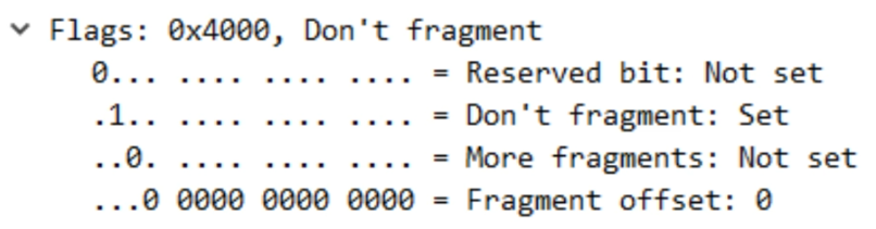
What if we did ping 192.168.1.2 size 10000 df-bit?
- Ping will fail and be dropped.
Questions
What is the fixed binary value of the first field of an IPv4 Header?
0100; first field is the version field.Which field will cause the packet to be dropped of it has a value of 0?
TTL. A hop of 0 will cause the packet to be dropped.How are errors in an IPv4 packet’s encapsulated data detected?
The encapsulated protocol (TCP, UDP) checks for errors.
(Common misconception is that the IPv4 Header Checksum field checks for errors, but it only checks for errors in the IPv4 Header itself).Which field of an IPv4 header is variable in length?
Options.
- Although the total length and IHL fields is used to represent the variable length, the field itself is fixed in length.
- Which bit will be set to 1 on all IPv4 packet fragments except the last fragment?
More fragment bit (Flags field)