Configure OSPF on the tunnel interfaces of R1 and R2, to allow PC1 and PC2 to communicate.
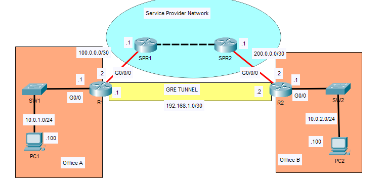
Both routers are connected via service provider network (SPN).
The GRE tunnel will create a direct connection. All traffic between R1 and R2 will still have to physically pass through the SPN. However, all packets will be encapsulated in additional headers to create a “virtual tunnel”.
GRE does not encrypt packets, so this configuration is insecure.
1. Configure a GRE tunnel to connect R1 and R2.
Specify a virtual tunnel interface. Then configure the tunnel source and destination. Then finally define an IP address for the tunnel itself.
1
2
3
4
5
6
7
8
9
10
11
12
13
14
15
16
17
R1(config)#interface tunnel 0
R1(config-if)# %LINK-5-CHANGED: Interface Tunnel0, changed state to up
R1(config-if)#do show ip int brief Interface IP-Address OK? Method Status Protocol GigabitEthernet0/0 10.0.1.1 YES NVRAM up up GigabitEthernet0/1 unassigned YES NVRAM administratively down down GigabitEthernet0/2 unassigned YES NVRAM administratively down down GigabitEthernet0/0/0 100.0.0.2 YES manual up up Tunnel0 192.168.1.1 YES manual up down Vlan1 unassigned YES unset administratively down down
R2(config-if)#do sh ip int brief Interface IP-Address OK? Method Status Protocol GigabitEthernet0/0 10.0.2.1 YES NVRAM up up GigabitEthernet0/1 unassigned YES NVRAM administratively down down GigabitEthernet0/2 unassigned YES NVRAM administratively down down GigabitEthernet0/0/0 200.0.0.2 YES manual up up Tunnel0 192.168.1.2 YES manual up down Vlan1 unassigned YES unset administratively down down
Tunnel interface for R1 and R2 are still down. Why?
There is no route from R2 to R1 via the tunnel destination: 100.0.0.2
R2(config-if)#do sh ip route Codes: L - local, C - connected, S - static, R - RIP, M - mobile, B - BGP D - EIGRP, EX - EIGRP external, O - OSPF, IA - OSPF inter area N1 - OSPF NSSA external type 1, N2 - OSPF NSSA external type 2 E1 - OSPF external type 1, E2 - OSPF external type 2, E - EGP i - IS-IS, L1 - IS-IS level-1, L2 - IS-IS level-2, ia - IS-IS inter area * - candidate default, U - per-user static route, o - ODR P - periodic downloaded static route
Gateway of last resort is not set
10.0.0.0/8 is variably subnetted, 2 subnets, 2 masks C 10.0.2.0/24 is directly connected, GigabitEthernet0/0 L 10.0.2.1/32 is directly connected, GigabitEthernet0/0 200.0.0.0/24 is variably subnetted, 2 subnets, 2 masks C 200.0.0.0/30 is directly connected, GigabitEthernet0/0/0 L 200.0.0.2/32 is directly connected, GigabitEthernet0/0/0
R2(config-if)#exit R2(config)# R2(config)#ip route 0.0.0.0 0.0.0.0 200.0.0.1 R2(config)# %LINEPROTO-5-UPDOWN: Line protocol on Interface Tunnel0, changed state to up
R2(config)#do sh ip route Codes: L - local, C - connected, S - static, R - RIP, M - mobile, B - BGP D - EIGRP, EX - EIGRP external, O - OSPF, IA - OSPF inter area N1 - OSPF NSSA external type 1, N2 - OSPF NSSA external type 2 E1 - OSPF external type 1, E2 - OSPF external type 2, E - EGP i - IS-IS, L1 - IS-IS level-1, L2 - IS-IS level-2, ia - IS-IS inter area * - candidate default, U - per-user static route, o - ODR P - periodic downloaded static route
Gateway of last resort is 200.0.0.1 to network 0.0.0.0
10.0.0.0/8 is variably subnetted, 2 subnets, 2 masks C 10.0.2.0/24 is directly connected, GigabitEthernet0/0 L 10.0.2.1/32 is directly connected, GigabitEthernet0/0 192.168.1.0/24 is variably subnetted, 2 subnets, 2 masks C 192.168.1.0/30 is directly connected, Tunnel0 L 192.168.1.2/32 is directly connected, Tunnel0 200.0.0.0/24 is variably subnetted, 2 subnets, 2 masks C 200.0.0.0/30 is directly connected, GigabitEthernet0/0/0 L 200.0.0.2/32 is directly connected, GigabitEthernet0/0/0 S* 0.0.0.0/0 [1/0] via 200.0.0.1
R1(config)#ip route 0.0.0.0 0.0.0.0 100.0.0.1 R1(config)# %LINEPROTO-5-UPDOWN: Line protocol on Interface Tunnel0, changed state to up
R1(config)#do sh ip route Codes: L - local, C - connected, S - static, R - RIP, M - mobile, B - BGP D - EIGRP, EX - EIGRP external, O - OSPF, IA - OSPF inter area N1 - OSPF NSSA external type 1, N2 - OSPF NSSA external type 2 E1 - OSPF external type 1, E2 - OSPF external type 2, E - EGP i - IS-IS, L1 - IS-IS level-1, L2 - IS-IS level-2, ia - IS-IS inter area * - candidate default, U - per-user static route, o - ODR P - periodic downloaded static route
Gateway of last resort is 100.0.0.1 to network 0.0.0.0
10.0.0.0/8 is variably subnetted, 2 subnets, 2 masks C 10.0.1.0/24 is directly connected, GigabitEthernet0/0 L 10.0.1.1/32 is directly connected, GigabitEthernet0/0 100.0.0.0/8 is variably subnetted, 2 subnets, 2 masks C 100.0.0.0/30 is directly connected, GigabitEthernet0/0/0 L 100.0.0.2/32 is directly connected, GigabitEthernet0/0/0 192.168.1.0/24 is variably subnetted, 2 subnets, 2 masks C 192.168.1.0/30 is directly connected, Tunnel0 L 192.168.1.1/32 is directly connected, Tunnel0 S* 0.0.0.0/0 [1/0] via 100.0.0.1
Ping now works via the tunnel.
1 2 3 4 5 6
R1(config)#do ping 192.168.1.2
Type escape sequence to abort. Sending 5, 100-byte ICMP Echos to 192.168.1.2, timeout is 2 seconds: .!!!! Success rate is 80 percent (4/5), round-trip min/avg/max = 0/3/10 ms
So although R1 and R2 aren’t directly connected; they will behave as if they are directly connected.
So what makes this a “tunnel”?
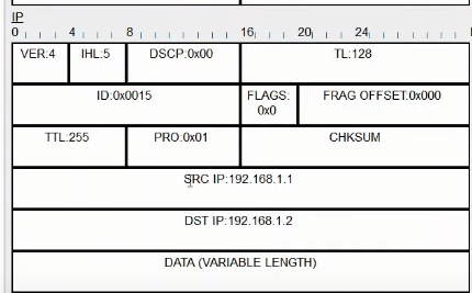
The ICMP ping is encapsulated with an IP header with IP SRC/IP DST of the tunnel interfaces.
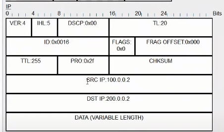
Additionally, with the IP header, is an addition of a GRE header.
And on top of the GRE header, is ANOTHER IP header, which contains the SRC IP of 100.0.0.2 (R1’s g0/0/0 interface) and R2’s IP address (200.0.0.2 R2’s g0/0/0 interface).
So a tunnel is encapsulated with an additional GRE and IP header, which is used to transport the packet over the Service Provider Network to reach R2.
2. Configure OSPF on the tunnel interfaces of R1 and R2, to allow PC1 and PC2 to communicate.
Virtual tunnels can be OSPF neighbors to share routes.
Ping statistics for 10.0.2.100: Packets: Sent = 4, Received = 0, Lost = 4 (100% loss),
When R1 and R2 become OSPF neighbors, they will learn each other routes and PC1 and PC2 can communicate over the virtual tunnel.
Enable OSPF on R1:
We enabled OSPF on the GRE tunnel interface AND the G0/0 interface, so it can tell R2 about its connected LAN.
Note* wildcard masks here are extremely specific, but any matching wildcard mask can work.
Also G0/0 should be made an passive interface, since no neighbors are connected to it.
1 2 3 4 5 6
R1(config)#router ospf 1 R1(config-router)#network 192.168.1.1 0.0.0.3 area 0 R1(config-router)# R1(config-router)#network 10.0.1.1 0.0.0.255 area 0 R1(config-router)# R1(config-router)#passive-interface g0/0
Enable OSPF on R2:
Same logic as R1
1 2 3 4 5 6 7 8 9
R2(config)#router ospf 1
R2(config-router)#network 192.168.1.2 0.0.0.3 area 0 10:35:13: %OSPF-5-ADJCHG: Process 1, Nbr 192.168.1.1 on Tunnel0 from LOADING to FULL, Loa R2(config-router)# R2(config-router)#network 10.0.2.1 0.0.0.255 area 0 R2(config-router)# R2(config-router)# R2(config-router)#passive-interface g0/0
We can see the OSPF routes on R2 (and R1)
1 2 3 4 5 6 7 8 9 10 11
10.0.0.0/8 is variably subnetted, 3 subnets, 2 masks O 10.0.1.0/24 [110/1001] via 192.168.1.1, 00:01:11, Tunnel0 C 10.0.2.0/24 is directly connected, GigabitEthernet0/0 L 10.0.2.1/32 is directly connected, GigabitEthernet0/0 192.168.1.0/24 is variably subnetted, 2 subnets, 2 masks C 192.168.1.0/30 is directly connected, Tunnel0 L 192.168.1.2/32 is directly connected, Tunnel0 200.0.0.0/24 is variably subnetted, 2 subnets, 2 masks C 200.0.0.0/30 is directly connected, GigabitEthernet0/0/0 L 200.0.0.2/32 is directly connected, GigabitEthernet0/0/0 S* 0.0.0.0/0 [1/0] via 200.0.0.1
Try the pings again.
1 2 3 4 5 6 7 8 9 10 11 12 13 14 15
C:\>ping 10.0.2.100
Pinging 10.0.2.100 with 32 bytes of data:
Request timed out. Reply from 10.0.2.100: bytes=32 time<1ms TTL=126 Reply from 10.0.2.100: bytes=32 time<1ms TTL=126 Reply from 10.0.2.100: bytes=32 time<1ms TTL=126
Ping statistics for 10.0.2.100: Packets: Sent = 4, Received = 3, Lost = 1 (25% loss), Approximate round trip times in milli-seconds: Minimum = 0ms, Maximum = 0ms, Average = 0ms