1. 1. show commands
  2. 2. CLI Passwords, Generic Commands - 4
  3. 3. Ethernet LAN Switching - 6
  4. 4. IPv4 Addressing (Assigning IPv4 Addresses)
  5. 5. Switch Interfaces (9)
  6. 6. Routing (Connected and Local Routes)
  7. 7. Subnetting
    1. 7.1. Subnetting Question 1 (Dividing Subnets)
    2. 7.2. Subnetting Question 2 (Dividing Subnets)
    3. 7.3. Subnetting Question 3 (Which subnet does this belong in?)
    4. 7.4. Subnetting Question 4 (Which subnet does this belong in?)
    5. 7.5. Subnetting Class B Networks Question 1
    6. 7.6. Subnetting Class B Networks Question 2
    7. 7.7. Subnetting Class B Network Question 3
    8. 7.8. Subnetting Class B Network Question 4
    9. 7.9. More Subnetting Questions
      1. 7.9.1. Question 1: You have been given 172.30.0.0/16 network. Company requires 100 subnets with at least 500 hosts per subnet. What prefix length should be used?
      2. 7.9.2. Question 2: What subnet does host 172.21.111.201/20 belong to?
      3. 7.9.3. Question 3: What is the broadcast address of the network 192.168.91.78/26?
      4. 7.9.4. Question 4: You divide the 172.16.0.0/16 network into 4 subnets of equal size. Identify the NETWORK and BROADCAST addresses of the 2nd subnet.
      5. 7.9.5. You divide the 172.30.0.0/16 network into subnets of 1000 hosts each. How many subnets are you able to make? —!!!!!!!!!!
    10. 7.10. Subnetting Class A Networks
      1. 7.10.1. Question 1: “You have been given the 10.0.0.0/8 network. You must create 2000 subnets which will be distributed to various enterprises. What prefix length must you use? How many host addresses (usable addresses) will be in each subnet?”
      2. 7.10.2. Question 2:
  8. 8. VLSM
  9. 9. VLANs (Access Ports)
  10. 10. VLANs (Trunk Configurations - manual)
  11. 11. Router on a Stick (ROAS)
  12. 12. Native VLAN Configurations on the Router
  13. 13. Multilayer Switches (Layer 3)
    1. 13.1. Multilayer Switch Configuration for Point-to-Point; Point-to-Point Link for Switch and Router
    2. 13.2. Now, Configure SVI Configuration
  14. 14. DTP/VTP : should be disabled (N)
    1. 14.1. DTP
    2. 14.2. VTP
  15. 15. STP (Analyzing STP)
    1. 15.1. Spanning Tree Protocol Determination
  16. 16. Spanning Tree - 2
  17. 17. RSTP (Rapid PVST+) (Kinda the same thing)
    1. 17.1. About RSTP
    2. 17.2. RSTP Determination
  18. 18. EtherChannel (Port Channel / LAG) and Load Balancing
    1. 18.1. Layer 3 Multi-Switches and EtherChannels
  19. 19. Dynamic Routing - 24
  20. 20. RIP and EIGRP - 25 (Configurations - (N))
    1. 20.1. RIP
      1. 20.1.1. RIP Configuration (N)
    2. 20.2. EIGRP: Enchanced Interior Gateway Routing Protocol
      1. 20.2.1. Wildcard Mask (Inverted Subnet Mask)
  21. 21. EIGRIP Configurations (N); Info (Y)
    1. 21.1. Generalized Steps for EIGRP Configurations
  22. 22. OSPF Part 1
  23. 23. OSPF - 2
    1. 23.1. Neighbor States
    2. 23.2. OSPF Neighbor Discovery and Formation
    3. 23.3. Criteria for Forming Neighbors
    4. 23.4. Maintenance of OSPF Neighbors
      1. 23.4.1. OSPF Neighbor Requirements
    5. 23.5. Enable OSPF Directly on an Interface without using the Network Command
  24. 24. OSPF - 3
    1. 24.1. DR/BDR Selection
  25. 25. FHRP (HSRP) Configuration (N)
    1. 25.1. HSRP
    2. 25.2. VRRP
    3. 25.3. GLBP
    4. 25.4. HSRP Configuration (N)
  26. 26. IPv6 Routing
  27. 27. ACL
    1. 27.1. Numbered ACL
    2. 27.2. Standard Named ACLs
    3. 27.3. Another way to configure numbered ACL (in named ACL config mode)
    4. 27.4. Resequencing ACL
    5. 27.5. Extended ACL
  28. 28. CDP and LLDP
    1. 28.1. CDP
    2. 28.2. LLDP
  29. 29. NTP
  30. 30. DNS
  31. 31. DHCP
  32. 32. SNMPv2c Configurations (N)
  33. 33. Syslog (N)
  34. 34. SSH, Console Line, Telnet
    1. 34.1. Layer 2 Switch - IP management
    2. 34.2. Telnet Configuration
    3. 34.3. SSH
  35. 35. FTP and TFTP
  36. 36. NAT
    1. 36.1. Static Nat
    2. 36.2. Dynamic NAT Configuration
    3. 36.3. PAT (NAT Overload)
  37. 37. QoS | PoE and VoIP
  38. 38. Port Security: Layer 2 (DHCP snooping, dynamic ARP inspection, port)
    1. 38.1. Port Security
    2. 38.2. DHCP Snooping
    3. 38.3. Dynamic ARP Inspection (DAI)
  39. 39. HSRP
  40. 40. VRF-lite (N)

Cisco Configuration Commands (Compiled)

show commands

Router

1
2
3
4
5
6
7
8
9
10
11
12
13
14
15
16
17
18
19
20
21
22
23
show running-config 
show startup-config

show ip interface brief
show ip route
show interfaces status
show vlan brief
show interfaces INTERFACE-ID switchport // shows administrative and operational mode

show vtp status

//Used for RIP, EIGRP, OSPF
show ip protocols
show ip protocols brief (?)

show ip ospf ?
show ip ospf database ## shows LSA(s) in LSDB
show ip ospf neighbor ## shows OSPF neighbors
show ip ospf interface ## views all interface details on ospf
show ip ospf interface INTERFACE-ID

show ipv6 int brief

Switch

1
2
3
show ip interface brief
show interfaces status

CLI Passwords, Generic Commands - 4

Enable password for privilege EXEC mode

1
2
//case-sensitive password; enable for prev EXEC mode; visible in running-conf
Router(config)#enable password PASSWORD

Copy configurations from RAM to NVRAM

1
2
3
Router(config)#write
Router(config)#write memory
Router(config)#copy running-config startup-config

Enable password-encryption

1
2
3
4
5
//Command will encrypt passwords such that its obscured in running-config; Uses CISCO Type 7
Router(config)#service password-encryption PASSWORD

//Uses Cisco Type 5 (MD5); preferred; takes precedence over `enable password`
Router(config)#enable secret PASSWORD

Ethernet LAN Switching - 6

Show MAC address table

1
2
3
4
5
6
7
8
9
10
11
12
13
14
15
16
SW1#show mac address-table

Mac Address Table
-------------------------------------------

Vlan Mac Address Type Ports
---- ----------- -------- -----
1 00e0.fc99.21f7 DYNAMIC Fa0/1
1 00d0.ba89.3f56 DYNAMIC Fa0/2
10 00a2.e599.40f0 DYNAMIC Fa0/5
10 00e0.fc99.21f7 STATIC Fa0/6
20 00af.573e.237b DYNAMIC Fa0/10
20 001d.eafe.33ac DYNAMIC Fa0/11
100 0025.bae5.76cf DYNAMIC Fa0/17

Total Mac Addresses for this criterion: 7

Clear MAC addresses

1
2
3
4
5
6
7
8
//Clears all dynamic MAC addresses
clear mac address-table dynamic

//Clear specific mac-addresses
clear mac address-table dynamic address MAC-ADDRESS

//Clear mac entries for a specific interface
clear mac address-table dynamic interface INTERFACE-ID

IPv4 Addressing (Assigning IPv4 Addresses)

Show command for each interface; routers are administratively down by default

1
2
3
4
5
6
7
8
//Status = layer 1 (physical) ; Protocol = layer 2 status 
R1#show ip interface brief
Interface IP-Address OK? Method Status Protocol
GigabitEthernet0/0 unassigned YES unset administratively down down
GigabitEthernet0/1 unassigned YES unset administratively down down
GigabitEthernet0/2 unassigned YES unset administratively down down
GigabitEthernet0/3 unassigned YES unset administratively down down
R1#

Show a specific interface

1
2
3
4
5
6
7
8
9
10
11
12
13
14
15
16
17
18
19
20
21
22
23
24
25
26
27
28
29
30
31
32
33
//Shows detailed information of interface
R1#show interfaces INTERFACE-ID

//e.g.,
R1#show interfaces g0/0
GigabitEthernet0/0 is up, line protocol is up
Hardware is iGbE, address is 0c1b.8444.f000 (bia 0c1b.8444.f000)
Internet address is 10.255.255.254/8
MTU 1500 bytes, BW 1000000 Kbit/sec, DLY 10 usec,
reliability 255/255, txload 1/255, rxload 1/255
Encapsulation ARPA, loopback not set
Keepalive set (10 sec)
Auto Duplex, Auto Speed, link type is auto, media type is RJ45
output flow-control is unsupported, input flow-control is unsupported
ARP type: ARPA, ARP Timeout 04:00:00
Last input 00:00:06, output 00:00:05, output hang never
Last clearing of "show interface" counters never
Input queue: 0/75/0/0 (size/max/drops/flushes); Total output drops: 0
Queueing strategy: fifo
Output queue: 0/40 (size/max)
5 minute input rate 0 bits/sec, 0 packets/sec
5 minute output rate 0 bits/sec, 0 packets/sec
167 packets input, 30159 bytes, 0 no buffer
Received 0 broadcasts (0 IP multicasts)
0 runts, 0 giants, 0 throttles
0 input errors, 0 CRC, 0 frame, 0 overrun, 0 ignored
0 watchdog, 0 multicast, 0 pause input
350 packets output, 39097 bytes, 0 underruns
0 output errors, 0 collisions, 2 interface resets
15 unknown protocol drops
0 babbles, 0 late collision, 0 deferred
1 lost carrier, 0 no carrier, 0 pause output
0 output buffer failures, 0 output buffers swapped out

Configure an IP Address

1
2
3
4
5
6
7
8
9
10
R1(config-if)#ip address 10.255.255.254 ?
A.B.C.D IP subnet mask

R1(config-if)#ip address 10.255.255.254 255.0.0.0
R1(config-if)#no shutdown
R1(config-if)#
*Dec 7 08:29:08.937: %LINK-3-UPDOWN: Interface GigabitEthernet0/0, changed state to up
*Dec 7 08:29:09.938: %LINEPROTO-5-UPDOWN: Line protocol on Interface GigabitEthernet0/0, changed state to up
R1(config-if)#

Configure a description per interface

1
2
R1(config)#int INTERFACE-ID
R1(config-if)#description DESCRIPTION

Show the descriptions configured on each interface

1
2
3
4
5
6
7
8
R1#show interfaces description 

R1#show interfaces description
Interface Status Protocol Description
Gi0/0 up up
Gi0/1 up up
Gi0/2 up up
Gi0/3 admin down down

Switch Interfaces (9)

Show command

1
2
3
4
5
6
7
8
9
10
11
12
13
14
15
16
17
18
19
20
SW1#show ip int brief 

//SWs are up/up by default if they are connected to another device
//Furthermore, down/down is not the same as administratively down (which are due to a shutdown command)
SW1#sh ip int br
Interface IP-Address OK? Method Status Protocol
Vlan1 unassigned YES unset up up
FastEthernet0/1 unassigned YES unset up up
FastEthernet0/2 unassigned YES unset up up
FastEthernet0/3 unassigned YES unset up up
FastEthernet0/4 unassigned YES unset up up
FastEthernet0/5 unassigned YES unset down down
FastEthernet0/6 unassigned YES unset down down
FastEthernet0/7 unassigned YES unset down down
FastEthernet0/8 unassigned YES unset down down
FastEthernet0/9 unassigned YES unset down down
FastEthernet0/10 unassigned YES unset down down
FastEthernet0/11 unassigned YES unset down down
FastEthernet0/12 unassigned YES unset down down

Another show command

1
2
3
4
5
6
7
8
9
10
11
12
13
14
15
SW1#show interfaces status
Port Name Status Vlan Duplex Speed Type
Fa0/1 connected 1 a-full a-100 10/100BaseTX
Fa0/2 connected trunk a-full a-100 10/100BaseTX
Fa0/3 connected 1 a-full a-100 10/100BaseTX
Fa0/4 connected 1 a-full a-100 10/100BaseTX
Fa0/5 notconnect 1 auto auto 10/100BaseTX
Fa0/6 notconnect 1 auto auto 10/100BaseTX
Fa0/7 notconnect 1 auto auto 10/100BaseTX
Fa0/8 notconnect 1 auto auto 10/100BaseTX
Fa0/9 notconnect 1 auto auto 10/100BaseTX
Fa0/10 notconnect 1 auto auto 10/100BaseTX
Fa0/11 notconnect 1 auto auto 10/100BaseTX
Fa0/12 notconnect 1 auto auto 10/100BaseTX

Another show command; more detailed.

1
2
3
4
5
6
7
8
9
10
11
12
13
14
15
16
17
18
19
20
21
22
23
24
25
26
SW1#show interfaces
FastEthernet0/1 is up, line protocol is up
Hardware is Fast Ethernet, address is 000c.2110.5542 (bia 000c.2110.5542)
SW1#show interfaces f0/1
FastEthernet0/1 is up, line protocol is up
Hardware is Fast Ethernet, address is 000c.2110.5542 (bia 000c.2110.5542)
Description: ## to R1 ##
MTU 1500 bytes, BW 100000 Kbit, DLY 100 usec,
reliability 255/255, txload 1/255, rxload 1/255
Full-duplex, 100Mb/s
Encapsulation ARPA, loopback not set
ARP type: ARPA, ARP Timeout 04:00:00
Last input 02:29:44, output never, output hang never
Last clearing of "show interface" counters never
Input queue: 0/75/0/0 (size/max/drops/flushes); Total output drops: 0
Queueing strategy: fifo
Output queue :0/40 (size/max)
5 minute input rate 0 bits/sec, 0 packets/sec
5 minute output rate 0 bits/sec, 0 packets/sec
269 packets input, 71059 bytes, 0 no buffer
Received 6 broadcasts, 0 runts, 0 giants, 0 throttles
0 input errors, 0 CRC, 0 frame, 0 overrun, 0 ignored
7290 packets output, 429075 bytes, 0 underruns
0 output errors, 3 interface resets
0 output buffer failures, 0 output buffers swapped out

Typically, auto-negotiation works fine.
Here’s how to configure the duplex and speed anyways.

1
2
3
4
5
6
7
8
9
10
11
12
13
SW1#conf t
Enter configuration commands, one per line. End with CNTL/Z.
SW1(config)#int f0/1
SW1(config-if)#speed ?
10 Force 10 Mbps operation
100 Force 100 Mbps operation
auto Enable AUTO speed configuration
SW1(config-if)#speed 100
SW1(config-if)#duplex ?
auto Enable AUTO duplex configuration
full Force full duplex operation
half Force half duplex operation
SW1(config-if)#duplex full

Routing (Connected and Local Routes)

Show routes;
Connected and local routes are automatically added for an interface configured with an IP address.

1
2
3
4
5
6
7
8
9
10
11
12
13
14
15
16
17
18
19
20
21
22
23
24
25
//Connected routes are for a specific network
//A local route is for the "host (R1)" itself.
R1#show ip route

Codes: L - local, C - connected, S - static, R - RIP, M - mobile, B - BGP
D - EIGRP, EX - EIGRP external, O - OSPF, IA - OSPF inter area
N1 - OSPF NSSA external type 1, N2 - OSPF NSSA external type 2
E1 - OSPF external type 1, E2 - OSPF external type 2
i - IS-IS, su - IS-IS summary, L1 - IS-IS level-1, L2 - IS-IS level-2
ia - IS-IS inter area, * - candidate default, U - per-user static route
o - ODR, P - periodic downloaded static route, H - NHRP, l - LISP
a - application route
+ - replicated route, % - next hop override, p - overrides from PfR

Gateway of last resort is not set

192.168.1.0/24 is variably subnetted, 2 subnets, 2 masks
C 192.168.1.0/24 is directly connected, GigabitEthernet0/2
L 192.168.1.1/32 is directly connected, GigabitEthernet0/2
192.168.12.0/24 is variably subnetted, 2 subnets, 2 masks
C 192.168.12.0/24 is directly connected, GigabitEthernet0/1
L 192.168.12.1/32 is directly connected, GigabitEthernet0/1
192.168.13.0/24 is variably subnetted, 2 subnets, 2 masks
C 192.168.13.0/24 is directly connected, GigabitEthernet0/0
L 192.168.13.1/32 is directly connected, GigabitEthernet0/0

Create a route to a network; ensure two way reachability

1
2
3
4
5
6
7
8
//Configure a route using the next-hop
R1(config)#ip route IP-ADDRESS NETMASK NEXT-HOP

//Configure a route using an exit-interface ; displays "directly connected"; relies on PROXY ARP
R1(config)#ip route IP-ADDRESS NETMASK EXIT-INTERFACE

//Specify both exit-interface and next-hop
R1(config)#ip route IP-ADDRESS NETMASK EXIT-INTERFACE NEXT-HOP

Configure a default route

1
2
//Default route is a route to 0.0.0.0/0
R1(config)#ip route 0.0.0.0 0.0.0.0 {[EXIT-INTERFACE] | [NEXT HOP]}

Subnetting

CIDR Notation Class C

Dotted Decimal CIDR Notation Host bits Usable Hosts
255.255.255.0 /24 8 x.x.x.00000000 2^8 - 2 = 254
255.255.255.128 /25 7 x.x.x.10000000 2^7 - 2 = 126
255.255.255.192 /26 6 x.x.x.11000000 2^6 - 2 = 62
255.255.255.224 /27 5 x.x.x.11100000 2^5 - 2 = 30
255.255.255.240 /28 4 x.x.x.11110000 2^4 - 2 = 14
255.255.255.248 /29 3 x.x.x.11111000 2^3 - 2 = 6
255.255.255.252 /30 2 x.x.x.11111100 2^2 - 2 = 2
255.255.255.254 /31 1 x.x.x.11111110 2^1 - 2 = 0 (2)
255.255.255.255 /32 0 x.x.x.11111111 0 (1)

For a point-to-point connection, it is possible to use a /31 mask, even though there are no host bits, we can assign the network address and the broadcast address to our two hosts specifically.
In reality, a /30 subnet mask would be used for a point-to-point.

Subnetting Question 1 (Dividing Subnets)

There are four switches, SW1 to SW4, each requiring accommodation for 45 hosts and connected to a central router R1. The task is to subnet the given 192.168.1.0/24 network appropriately.
Divide the 192.168.1.0/24 network into four subnets that can accommodate the number of hosts required.

  1. Determine the number of networks required.

    1. 45 + 2 = 47
    2. 47 * 4 = 188 (well within the range of a class C subnet which has 256 subnets)
  2. How to calculate the subnets we need to make?

    1. /30 gives us 2^2 - 2 = 4 usable addresses
    2. /29 gives us 2^2 - 2 = 6 usable addresses
    3. /28 gives us 2^4 - 2 = 14 usable addresses
    4. /27 gives us 2^5 - 2 = 30 usable addresses
    5. /26 gives us 2^6 - 2 = 62 usable addresses – this provides us more than we need.
  3. Now calculate each subnet

    • Subnet 1: 192.168.1.0 - 192.168.1.63, where
      • 192.168.1.0 = network addresses
      • 192.168.1.63 = broadcast address
      • 192.168.1.1 = first usable
      • 192.168.1.62 = last usable
    • Subnet 2: 192.168.1.64 - 192.168.1.127 (can simply look at the last bit in the network to determine the going range)
      • If we were to do it “manually”…:
        • 192.168.1.64 = 11000000.10101000.00000001.[01(000000)] = network address
        • 11000000.10101000.00000001.[01(000000)] => x.x.x.[01(111111)] = x.x.x.127
    • Subnet 3: 192.168.1.128 - 192.168.1.191
    • Subnet 4: 192.168.1.192 - 192.168.1.255

Subnetting Question 2 (Dividing Subnets)

Divide the 192.168.255.0/24 network into five equal-sized subnets.

  1. 5 subnets are required.
    • /26 is 6 host bits. 2^6 = 64; 64 * 5 = 320, which is well over allocated class C host range.
    • /27 is 5 host bits. 2^5 = 32; 32 * 5 = 160, which is within range.
      Next, calculate each subnet. – can easily use the network range bit, which is +32.
  2. 192.168.255.0 - 192.168.255.31 ()
  3. 192.168.255.32 - 192.168.255.63 IMPORTANT!, it’s not .64!!!!!!!!
  4. 192.168.255.64 - 192.168.255.95
  5. 192.168.255.96 - 192.168.255.127
  6. 192.168.255.128 - 192.168.255.159

Subnetting Question 3 (Which subnet does this belong in?)

~~What subnet does host 192.168.5.57/27 belong to?
- /27 indicates 3 ‘borrowed bits’ from x.x.x.001(0000), the 5th bit is 32; so increments of 32. ~
~- 0 -> 32 -> 64, so 192.168.5.57 belongs in the 192.168.5.32/27 subnet (2nd subnet)

A more ‘formal way’ to do this is as follows:

  1. x.x.x.(001)(11001) = x.x.x.57
  2. Change all the host bits back to 0 => x.x.x.(001)00000 => x.x.x.32

Subnetting Question 4 (Which subnet does this belong in?)

~~What subnet does host 192.168.29.219/29 belong to?~
- /29 => x.x.x.00001000 => 4th bit is 16; so increments of 16. ~
~- 160, 176, 192, 208, 224, 240

~- So 219 is between 208 and 224, so the subnet ID is 192.168.29.208/29. ~~

The more formal way is converting .219 into binary (given that this is a class C address)

  • x.x.x.11011011 => /29 indicates 5 borrowed bits and 3 host bits => x.x.x.(11011)(011)
  • Now set the host bits to 0 => x.x.x.(11011)000 => x.x.x.208

Subnetting Class B Networks Question 1

Create 80 subnets with the 172.16.0.0/16 network. What prefix length should be used?

  • The same methods apply to class B as if they were class A, except we begin at the 3rd octet.

  • xxxxxxxx.xxxxxxxx.00000000.00000000 /16

  • xxxxxxxx.xxxxxxxx.10000000.00000000 /17 // 2 subnets

  • xxxxxxxx.xxxxxxxx.11000000.00000000 /18 // 4 subnets

  • xxxxxxxx.xxxxxxxx.11100000.00000000 /19 // 8 subnets

  • xxxxxxxx.xxxxxxxx.11110000.00000000 /20 // 16 subnets

  • xxxxxxxx.xxxxxxxx.11111000.00000000 /21 // 32 subnets

  • xxxxxxxx.xxxxxxxx.11111100.00000000 /22 // 64 subnets

  • xxxxxxxx.xxxxxxxx.11111110.00000000 /23 // 128 subnets

  • xxxxxxxx.xxxxxxxx.11111111.00000000 /24 // 256 subnets

  • xxxxxxxx.xxxxxxxx.11111111.10000000 /25 // 512 subnets

  • Answer: The prefix length should be /23.

Subnetting Class B Networks Question 2

Create 500 subnets with the 172.22.0.0/16 network. What prefix length should be used?

  • xxxxxxxx.xxxxxxxx.00000000.00000000 /16

  • xxxxxxxx.xxxxxxxx.10000000.00000000 /17 // 2 subnets

  • xxxxxxxx.xxxxxxxx.11000000.00000000 /18 // 4 subnets

  • xxxxxxxx.xxxxxxxx.11100000.00000000 /19 // 8 subnets

  • xxxxxxxx.xxxxxxxx.11110000.00000000 /20 // 16 subnets

  • xxxxxxxx.xxxxxxxx.11111000.00000000 /21 // 32 subnets

  • xxxxxxxx.xxxxxxxx.11111100.00000000 /22 // 64 subnets

  • xxxxxxxx.xxxxxxxx.11111110.00000000 /23 // 128 subnets

  • xxxxxxxx.xxxxxxxx.11111111.00000000 /24 // 256 subnets

  • xxxxxxxx.xxxxxxxx.11111111.10000000 /25 // 512 subnets

  • Answer: Use /25 prefix length.

Subnetting Class B Network Question 3

You have been given the 172.18.0.0/16 network. Your company requires 250 subnets with the same number of hosts per subnet. What prefix length should you use?

8 borrowed bits = 256, which is the closest to meeting the requirement.

x.x.(11111111).00000000 => 16 + 8 = /24 prefix length

Subnetting Class B Network Question 4

What subnet does host 172.25.217.192/21 belong to?

  • Same concept as class A, except now we include in the class B (3rd) octet.
  • Convert to dotted decimal: x.x.217.192 => x.x.11011001.11000000 => x.x.(11011)(001.11000000)
  • Convert all host bits to 0: x.x.(11011)000.00000000 => x.x.216.0/21 subnet, which is the same as 172.25.216.0/21

More Subnetting Questions

Question 1: You have been given 172.30.0.0/16 network. Company requires 100 subnets with at least 500 hosts per subnet. What prefix length should be used?

  • Right off the bat, Class C subnets are out of the question. The smallest subnet 2 will likely support only 128 - 2 = 126 hosts.
  • Class B subnets should be used here.
  • given the 100 subnet requirement…it should be… /16 (0), /17 (2), … 7 borrowed bits… so /23 should be used.
    • 9 hosts bits allows for 2^9 - 2 = 510 usable addresses.

Question 2: What subnet does host 172.21.111.201/20 belong to?

- 64 + 32 = 96 
- 96 + 8 = 104
- 104 + 4 = 108
- 108 + 2 = 110
- 110 + 1 = 111

Given /20 for a class B subnet, this means 4 borrowed bits, so…
x.x.01101111.xxxxxxxx => I can skip finding the binary form of 201 because /20 is isolated within the 3rd octet.

x.x.(0110)1111.xxxxxxxx => x.x.(0110)0000.xxxxxxxx => x.x.96.xxxxxxxx

Subnet ID: 172.21.96.0/20

Question 3: What is the broadcast address of the network 192.168.91.78/26?

x.x.x.01001100 => x.x.x.(01)001100 => broadcast is all 1’s for host bits => x.x.x.(01)111111 => 192.168.91.127/26

Another way I did it is:

1
2
3
4
5
6
7
8
9
10
Class B, so...
- xxxxxxxx.xxxxxxxx.01011011.xxxxxxxx
- /26 is borrowing 10 bits... would need to calculate the last octet in this case as well
- xxxxxxxx.xxxxxxxx.01011011.01001110
- So first 10 bits would be...
- xxxxxxxx.xxxxxxxx.(01011011.01)001110
- xxxxxxxx.xxxxxxxx.91.64/26 (this would be the subnet)
- Hence, the broadcast address will be the last address of this subnet... **which I have no idea how to calculate.**
- I assume it'd be - xxxxxxxx.xxxxxxxx.(01011011.01)(111111)
- So 192.168.91.127/26

Question 4: You divide the 172.16.0.0/16 network into 4 subnets of equal size. Identify the NETWORK and BROADCAST addresses of the 2nd subnet.

Prefix Length Number of Subnets Number of Hosts per Subnet Total Number of Hosts…
/17 2 32766 32768
/18 4 16382 16384
/19 8 8190 8192
/20 16 4094 4096
/21 32 2046 2048
/22 64 1022 1024
/23 128 510 512
/24 256 254 256
/25 512 126 128
/26 1024 62 64
/27 2048 30 32
/28 4096 14 16
/29 8192 6 8
/30 16384 2 4
/31 32768 0 (2) 2
/32 65536 0 (1) 1

4 subnets? Should be 2 borrowed bits (which is equal to 4 subnets).
Therefore, it’s /18 prefix.

x.x.(00)xxxxxx.xxxxxx (notice that the 2 borrowed bits, 00, 01, 10, 11, – are the only possible options)
The 2nd subnet would be 01, which is x.x.(01)xxxxxx.xxxxxx.

Network address is 172.16.64.0.
The broadcast address would be all 1’s in host bits. So, x.x.x(01)111111.11111111 = 172.16.127.255 (?)

You divide the 172.30.0.0/16 network into subnets of 1000 hosts each. How many subnets are you able to make? —!!!!!!!!!!

If we don’t have access to the chart,

1
2
3
4
5
6
7
8
9
- Even if we don't know it, we can start at /32.
- /32 = 0 (1)
- /31 = 0 (2)
- /30 = 4 (4 addresses, 2 hosts)
- /29 = 8
- ... 16, 32, 64, 128, 256, 512,
- /22 = 1024 - 2 = 1022 hosts... (10 borrowed bits FROM THE RIGHT TO LEFT)
- /22 in subnets is... 6 bits so... 2 (/17) , 4, 8, 16, 32, 64 (/22)
- Answer: 64 subnets. (because 6 borrowed bits)

Actually, we can just do it normally.

2^n - 2 = 1000~ ? , where n = HOST bits (not network bits). Need about 10 host bits.
2^1 - 2 = 1024 - 2 = 1022;

Okay. We’re left with 6 borrowed bits.

x.x.x.(xxxxxx)(xx.xxxxxxxx)

So, if the prefix is /22, then the amount of subnets is therefore 2,4,6…64 subnets.

Subnetting Class A Networks

Question 1: “You have been given the 10.0.0.0/8 network. You must create 2000 subnets which will be distributed to various enterprises. What prefix length must you use? How many host addresses (usable addresses) will be in each subnet?”

  1. Let’s see how many network bits we need to create 2000 subnets.
    1. 2, 4, 8, 16, 32, 64, 128, 256, 512, 1024, 2048 => 11!
  2. x.(xxxxxxxx.xxx)xxxxx.xxxxxxxx = /19 is the prefix length.
  3. There are 13 host bits remaining. So 2^13 - 2 = 8192 - 2 = 8190 host.

Question 2:

PC1 has an IP address of 10.217.182.223/11.
Identify the following for PC1’s subnet:

  1. Network address:
  2. Broadcast address:
  3. First usable address:
  4. Last usable address:
  5. Number of host (usable) addresses:”

x.11011001.xxxxxxxx.xxxxxxxxx ; given the /11 subnet, we don’t technically need the rest.
x.(110)11001.xxxxxxxx.xxxxxxxxx ; /11 is 3 borrowed bits.

  1. Network address: x.(110)00000.00000000.00000000 => 10.192.0.0/11
  2. Broadcast address: x.(110)11111.11111111.11111111 => 10.223.255.255/11
  3. First usable: 10.192.0.1
  4. Last usable address: 10.223.255.254
  5. Number of host (usable addresses): 21 host bits => 2^21 - 2 = 2,097,150 hosts

VLSM

  1. Assign the largest subnet a the start of the address space.
  2. Assign the 2nd largest after.
  3. Repeat until largest to smallest.

Given 192.168.1.0/24 use VLSM to create 5 subnets for all hosts.

Tokyo LAN A (110) -> Toronto LAN B (45)-> Toronto LAN A (29) -> Tokyo LAN B (8) -> P2P (1)

Tokyo LAN A:

1
2
3
4
5
6
7
8
9
10
11
110 hosts, means 2,4,8,16,32,64,128, which is 7 host bits; leaving us with 1 network bit in the /24 network. 
A /25 prefix length is used.
Network address is 192.168.1.0/25.

Broadcast address is as follows: x.x.x.(0)0000000 => x.x.x.(0)1111111 => x.x.x.127 => 192.168.1.127/25

Network address: 192.168.1.0/25
Broadcast address: 192.168.1.127/25
First usable address 192.168.1.1
Last usable address: 192.168.1.126
Total number of usable host addresses: 2^7 - 2 = 126

Toronto LAN B

1
2
3
4
5
6
7
8
9
10
11
12
45 hosts means 2,4,8,16,32,64, which is 6 host bits; leaving us with 2 network bits in the /24 network.
A /26 prefix length is used.

The network address is the address after the previous subnet's broadcast address: 192.168.1.128/26

Broadcast address is as follows: x.x.x.(10)000000 => x.x.x.(10)111111 => .191

Network address: 192.168.1.128/26
Broadcast address: 192.168.1.191/26
First usable address 192.168.1.129/26
Last usable address: 192.168.1.190/26
Total number of usable host addresses: 2^6 - 2 = 62

Toronto LAN A

1
2
3
4
5
6
7
8
9
10
11
12
29 hosts means 2,4,8,18,32, which is 5 host bits; leaving us with 3 network bits in the /24 network.
A /27 prefix length is used.

The network address is the address after the previous subnet's broadcast address: 192.168.1.192/27

Broadcast address is as follows: x.x.x.(110)00000 => x.x.x.(110)11111 => .223

Network address: 192.168.1.192/27
Broadcast address: 192.168.1.223/27
First usable address 192.168.1.193/27
Last usable address: 192.168.1.222/27
Total number of usable host addresses: 2^5 - 2 = 30

Tokyo LAN B

1
2
3
4
5
6
7
8
9
10
11
12
8 hosts means 2,4,8,16, which is 4 host bits; leaving us with 4 network bits in the /24 network. 
A /28 prefix is used.

The network address is the address after the previous subnet's broadcast address: 192.168.1.224/28

Broadcast address is as follows: x.x.x.(1110)0000 => x.x.x.(1110)1111 => .239

Network address: 192.168.1.224/28
Broadcast address: 192.168.1.239/28
First usable address 192.168.1.225/28
Last usable address: 192.168.1.238/28
Total number of usable host addresses: 2^4 - 2 = 14

P2P Between R1 and R2

1
2
3
4
5
6
7
8
9
10
11
P2P connections should use a /30 network, which leaves us with 2 host bits.

The network address is the address after the previous subnet's broadcast address: 192.168.1.240/30

The broadcast address is x.x.x.(111100)00 => x.x.x.(111100)11 => .243

Network address: 192.168.1.240/30
Broadcast address: 192.168.1.243/30
First usable address 192.168.1.241/30
Last usable address: 192.168.1.242/30
Total number of usable host addresses: 2^2 - 2 = 2

VLANs (Access Ports)

After configuring subnets and default gateways on end hosts, (and setting router interfaces to their respective default gateway for each planned VLAN…)

Show VLANs

1
2
//All vlans are in in VLAN 1 by default; 1002 - 1005 exist by deault and cannot be deleted.
SW1#show vlan brief

VLAN Configuration

Assign VLAN(s) to interfaces

1
2
3
4
5
6
7
8
9
10
11
12
13
SW1(config)#interface range g1/0 - 3
SW1(config-if-range)#switchport mode access // ports are usually by default access, but good practice
SW1(config-if-range)#switchport access vlan 10 // vlans that do not exist are created automatically
% Access VLAN does not exist. Creating vlan 10
SW1(config-if-range)#interface range g2/0 - 2
SW1(config-if-range)#switchport mode access
SW1(config-if-range)#switchport access vlan 20
% Access VLAN does not exist. Creating vlan 20
SW1(config-if-range)#interface range g3/0 - 3
SW1(config-if-range)#switchport mode access
SW1(config-if-range)#switchport access vlan 30
% Access VLAN does not exist. Creating vlan 30
SW1(config-if-range)#

Configure VLANs

1
2
3
//Define a name
SW1(confiog)#vlan VLAN-ID
SW1(config-vlan)#name NAME

VLANs (Trunk Configurations - manual)

Manually configure interface as a trunk;
Modern switches do not support ISL, but for switches that do, you’d need to configure the encapsulation mode first; switches that only support dot1q will not need to do this

1
2
3
4
5
6
7
8
9
10
11
12
SW1(config)#interface g0/0
SW1(config-if)#switchport mode trunk
Command rejected: An interface whose trunk encapsulation is "Auto" can not be configured to "trunk" mode.
SW1(config-if)#switchport trunk encapsulation ?
dot1q Interface uses only 802.1q trunking encapsulation when trunking
isl Interface uses only ISL trunking encapsulation when trunking
negotiate Device will negotiate trunking encapsulation with peer on interface

SW1(config-if)#switchport trunk encapsulation dot1q
SW1(config-if)#switchport mode trunk
SW1(config-if)#

Show command

1
2
3
4
5
6
7
8
9
10
11
12
13
14
SW1#show interfaces trunk

Port Mode Encapsulation Status Native vlan
Gi0/0 on 802.1q trunking 1

Port Vlans allowed on trunk
Gi0/0 1-4094

Port Vlans allowed and active in management domain
Gi0/0 1,10,30

Port Vlans in spanning tree forwarding state and not pruned
Gi0/0 1,10,30
SW1#

Configured VLAN Allowed; configuring allowed VLANs is good for security and performance

1
2
3
4
5
6
7
8
SW1(config)#interface g0/0
SW1(config-if)#switchport trunk allowed vlan ?
WORD VLAN IDs of the allowed VLANs when this port is in trunking mode
add add VLANs to the current list // note* adding a VLAN to allowed, does not "create/activate" the VLAN
all all VLANs
except all VLANs except the following
none no VLANs
remove remove VLANs from the current list

Change the native VLAN; ensure NATIVE VLAN matches between switches

1
SW1(config-if)#switchport trunk native vlan VLAN-ID

Difference between show vlan brief and show interfaces trunk

  • Interfaces configured with trunk ports will NOT show up in show vlan brief; Use show interfaces trunk
    1
    2
    3
    4
    5
    6
    7
    8
    9
    10
    11
    12
    13
    14
    15
    16
    17
    18
    19
    20
    21
    22
    23
    24
    25
    26
    27
    28
    29
    30
    SW1#show vlan brief

    VLAN Name Status Ports
    ---- -------------------- ---------- -------------------------------------
    1 default active Gi1/1, Gi1/2, Gi1/3, Gi2/0
    Gi2/1, Gi2/2, Gi2/3, Gi3/0
    Gi3/1, Gi3/2, Gi3/3
    10 ENGINEERING active Gi0/1, Gi0/2
    30 SALES active Gi0/3, Gi1/0
    1002 fddi-default act/unsup
    1003 token-ring-default act/unsup
    1004 fddinet-default act/unsup
    1005 trnet-default act/unsup
    SW1#


    SW1(config-if)#do show interfaces trunk

    Port Mode Encapsulation Status Native vlan
    Gi0/0 on 802.1q trunking 1001

    Port Vlans allowed on trunk
    Gi0/0 10,30

    Port Vlans allowed and active in management domain
    Gi0/0 10,30

    Port Vlans in spanning tree forwarding state and not pruned
    Gi0/0 10,30
    SW1(config-if)#

Router on a Stick (ROAS)

Inter-VLAN routing is achieved via packet routes that are sent to the switch, then routed to a router. The router identifies the encapsulation (dot1q/ISL) tag via the VID, then routes it to the sub-interfaces as if they were individual interfaces.

Enter sub-interface configuration mode
Method 1: For sub-interfaces

1
2
3
4
5
//Remember that router intefaces are shutdown by default; enable via `no shutdown` in the base interface

R1(config)#int g0/0.10 // sub-interface does NOT have to match the VLAN number, but it's helpful
R1(config-subif)#encapsulation dot1q VLAN-ID // frames arriving with VLAN-ID matching will be sent to g0/0.10
R1(config-subif)#ip address IP-ADDRESS SUBNET-MASK // usually the default-gateway for end hosts

Native VLAN Configurations on the Router

Method 1: Configuring a Native VLAN on a sub-interface (assuming the IP address is already configured)
The configuration below achieves the goal that packets that are destined for VLAN 10 will not be tagged with the dot1q frame in the ethernet frame. Assuming that switches are configured with the same native VLAN, untagged frames will be routed to their native configured VLAN; achieves efficiency, but security issue.

1
2
3
R1(config)#int g0/0.10
R1(config-subif)#encapsulation dot1q 10 native
R1(config-subif)#

Method 2: The configuration here already assumes that we set up sub-interfaces with encapsulation and dot1q.
So, we simply change the sub-interface (and its respective VLAN) to a regular interface and IP address/gateway.

1
2
3
4
5
6
7
8
9
10
11
12
13
14
15
16
17
18
19
20
21
22
R1(config)#no interface g0/0.10
R1(config)#interface g0/0
R1(config-if)#ip address 192.168.1.62 255.255.255.192
R1(config-if)#

-Configure the IP address for the native VLAN on the router’s physical interface (the encapsulation dot1q vlan-id command is not necessary)

!
interface GigabitEthernet0/0
ip address 192.168.1.62 255.255.255.192
duplex auto
speed auto
media-type rj45
!
interface GigabitEthernet0/0.20
encapsulation dot1Q 20
ip address 192.168.1.126 255.255.255.192
!
interface GigabitEthernet0/0.30
encapsulation dot1Q 30
ip address 192.168.1.190 255.255.255.192
!

Multilayer Switches (Layer 3)

  • Introduces switch virtual interfaces (SVI).
  • Each PC should be configured to use the SVI (not the router) as their gateway address.
  • In addition to SVI, we can also configure switch interfaces to act like router interfaces.

Multilayer switches are the preferred method of inter-VLAN routing in a busy network.
In ROAS, end points were configured to use the router as the default gateway. Instead, configure the default-gateway to be the switch virtual interface (SVI).

Then what about routing traffic to the internet not meant for any VLAN?

  • We can configure IP addresses between the multilayer switch and router. Then create a default route in the routing table (like a router).

Swap a sub-interface trunk router with a a multilayer switch Point-to-Point configuration

1
2
3
4
5
6
7
8
// disable router's ROAS configuration if configured. 
// for example
R1(config)#no interface g0/0.10
R1(config)#no interface g0/0.20
R1(config)#no interface g0/0.30

// set interface to default settings
R1(config)#default interface INTERFACE
1
2
3
//Configure a regular IP address as normal for a P2P
R1(config)#interface g0/0
R1(config-if)#ip address IP-ADDRESS SUBNET-MASK

Multilayer Switch Configuration for Point-to-Point; enable multilayer switch to handle inter-VLAN routing

  • Here, we enable ip routing on a switch for layer 3 functionality, and also change a switch port to a “routed port (router port)”

    1
    2
    3
    4
    5
    6
    7
    8
    9
    10
    11
    12
    13
    14
    15
    16
    17
    18
    19
    20
    21
    22
    23
    24
    25
    26
    //If already configured, reset
    SW2(config)#default interface INTERFACE-ID

    // enables Layer 3 routing on the switch ; DO NOT FORGET
    SW2(config)#ip routing

    // configures the interface as a "routed port" instead of a switch port;
    SW2(config)#interface INTERFACE-ID
    SW2(config-if)#no switchport

    // now we can configure an IP address on the interface like a regular router interface
    SW2(config-if)#ip address IP-ADDRESS SUBNET-MASK


    SW2(config-if)#do show ip interface brief
    Interface IP-Address OK? Method Status Protocol
    GigabitEthernet0/0 unassigned YES unset up up
    GigabitEthernet0/2 unassigned YES unset up up
    GigabitEthernet0/3 unassigned YES unset up up
    GigabitEthernet0/1 192.168.1.193 YES manual up up
    GigabitEthernet1/0 unassigned YES unset up up
    GigabitEthernet1/1 unassigned YES unset up up
    GigabitEthernet1/2 unassigned YES unset up up
    GigabitEthernet1/3 unassigned YES unset up up
    GigabitEthernet2/0 unassigned YES unset up up
    GigabitEthernet2/1 unassigned YES unset up up
  • Configure a default route so that traffic meant for the internet is sent to the router (given that SW and R are P2P)

    1
    SW2(config)#ip route 0.0.0.0 0.0.0.0 NEXT-HOP

Now, Configure SVI Configuration

SVI’s here are used for default gateways, much like a router. So instead of sub-interfaces in routers, switches can just create SVIs.

1
2
3
4
5
6
7
8
9
10
11
12
// creates SVI for VLAN 10 // SVI's are shutdown by default; to enable use 'no shutdown'
SW2(config)#interface vlan 10
SW2(config-if)#ip address IP-ADDRESS SUBNET-MASK
SW2(config-if)#no shutdown

SW2(config)#interface vlan 20
SW2(config-if)#ip address IP-ADDRESS SUBNET-MASK
SW2(config-if)#no shutdown

SW2(config)#interface vlan 30
SW2(config-if)#ip address IP-ADDRESS SUBNET-MASK
SW2(config-if)#no shutdown

Conditions for SVI to be up/up

  1. The VLAN must exist on the switch. SVI’s do not automatically create a VLAN on the switch.
  2. The switch must have at least one access port in the VLAN up/up state, AND/OR one trunk port that allows the VLAN that is in an up/up state.
  3. The VLAN must not be shutdown.
  4. The SVI must not be shutdown.

DTP/VTP : should be disabled (N)

DTP

DTP will not form a trunk with a router, PC, etc. Switchports here will be in access mode by default.

1
2
3
4
5
6
7
8
9
10
11
SW2(config-if)#switchport mode ?
access Set trunking mode to ACCESS unconditionally
dot1q-tunnel set trunking mode to TUNNEL unconditionally
dynamic Set trunking mode to dynamically negotiate access or trunk mode
private-vlan Set private-vlan mode
trunk Set trunking mode to TRUNK unconditionally

SW2(config-if)#switchport mode dynamic ?
auto Set trunking mode dynamic negotiation parameter to AUTO
desirable Set trunking mode dynamic negotiation parameter to DESIRABLE

DTP will auto-negotiate encapsulation mode for ISL (first) or 802.1Q (if available)

1
2
3
4
5
6
7
8
9
10
11
12
13
14
15
16
17
18
19
SW1(config-if)#switchport mode dynamic desirable
SW1(config-if)#do show interfaces g0/0 switchport
Name: Gi0/0
Switchport: Enabled
Administrative Mode: dynamic desirable
Operational Mode: trunk
Administrative Trunking Encapsulation: negotiate
Operational Trunking Encapsulation: isl
Negotiation of Trunking: On
--------------------------------------------------------------------------------------------
SW2(config-if)#switchport mode dynamic desirable
SW2(config-if)#do show interfaces g0/0 switchport
Name: Gi0/0
Switchport: Enabled
Administrative Mode: dynamic desirable
Operational Mode: trunk
Administrative Trunking Encapsulation: negotiate
Operational Trunking Encapsulation: isl
Negotiation of Trunking: On

Disable auto-negotiate

1
2
3
4
5
6
//disable auto-negotiation as follows: 
switchport nonegotiate

OR

switchport mode access

VTP

  • VTP is a virtual LAN trunking protocol used to shared VLAN information between devices; switches act as central VTP servers that advertise their VLAN databases. (VTP does not assign vlans to interfaces )

  • VTP is designed for large networks, but it’s not recommended.

    1
    2
    3
    4
    5
    6
    7
    8
    9
    10
    11
    12
    13
    14
    15
    16
    17
    18
    SW1#show vtp status
    VTP Version capable : 1 to 3
    VTP version running : 1
    VTP Domain Name :
    VTP Pruning Mode : Disabled
    VTP Traps Generation : Disabled
    Device ID : c0c9.f956.1300
    Configuration last modified by 0.0.0.0 at 0-0-00 00:00:00
    Local updater ID is 0.0.0.0 (no valid interface found)

    Feature VLAN:
    VTP Operating Mode : Server
    Maximum VLANs supported locally : 1005 // VTPv1/v2 do not support extended VLAn range (1006-4094)
    Number of existing VLANs : 5
    Configuration Revision : 0
    MD5 digest : 0x57 0xCD 0x40 0x65 0x63 0x59 0x47 0xBD
    0x56 0x9D 0xA4 0x3E 0xA5 0x69 0x35 0xBC

  • Cisco switches operate VTP server mode by default

  • VTP servers and clients will sync with each other with the highest revision number (if in the same domain)

  • VTP Transparent does not participate in the VTP domain (does not sync VLAN database)

    • Transparent mode forwards other VTP advertisements, but will not send its own database advertisements.
  • VTP Client mode cannot create VLANs

  • How to reset revision domain? Change domain name to an unused, or change VTP mode to transparent.

  • VTPv1/v2 do not support extended VLAN range (1006-4094)

1
2
3
4
5
6
7
8
9
10
11
12
13
//COMMANDS
vtp mode server
vtp mode client
vtp mode transparent
vtp domain NAME
show vtp status


vtp version NUMBER(1/2/3)


sh int f0/1 switchport // checks specific interfaces for dtp/vtp

Show

1
show vtp status 

STP (Analyzing STP)

  • Hello BDPU’s are sent by forwarding states; it indicates to the receiving interface that the connected device is a switch; since routers, PCs, (etc), do not send Hello BDPUs.
    • Interfaces that do not receive BPDU’s can safely go into forwarding mode.
  • Originally, a bridge ID is the bridge priority (32768) + MAC address.
    • Bridge priority became => bridge priority + extended system ID (VLAN ID)
      • Why add VLAN ID? ; Cisco switches use PVST, which runs a separate STP instance in each VLAN, so difference interfaces can be forwarding/blocking.
    • Why is the bridge priority 32768? 16 bits for bridge priority => most significant bit set to 1.
      • But actually, since VLAN ID default is 1; it’s 32768 + 1 = 32769
    • You can only change the bridge ID by 4096? Why? Since extended system ID cannot change (VLAN ID). The 4th bit of the far most 16th bit is 4096.
Bridge Priority 32768 16384 8192 4096
Binary Value 0 1 1 1
Extended System ID (VLAN ID) 2048 1024 512 256 128 64 32 16 8 4 2 1
Binary Value 0 0 0 0 0 0 0 0 0 0 0 1

28673 (16384 + 8192 + 4096 + 1)

  • In 802.1D, all interfaces on the root bridge are designated ports.
  • When a switch is powered on, it assumes root bridge; a lower bridge ID (superior BPDU) will force it give up its position.
STP Port State Send/Receive BPDUs Frame forwarding (regular traffic) MAC address learning Stable/Transitional
Blocking NO/YES NO NO Stable
Listening YES/YES NO NO Transitional
Learning YES/YES NO YES Transitional
Forwarding YES/YES YES YES Stable
Disabled NO/NO NO NO Stable

Spanning Tree Protocol Determination

  1. One switch is elected as the root bridge. All ports on the root bridge are designated ports (forwarding state). Root bridge selection:
    1: Lowest bridge ID

  2. Each remaining switch will select ONE of its interfaces to be its root port (forwarding state). Ports across from the root port are always designated ports.
    Root port selection:
    1: Lowest root cost
    2: Lowest neighbor bridge ID
    3: Lowest neighbor port ID

  3. Each remaining collision domain will select ONE interface to be a designated port (forwarding state). The other port in the collision domain will be non-designated (blocking)
    Designated port selection:
    1: Interface on switch with lowest root cost *** compare the routes
    2: Interface on switch with lowest bridge ID


Show commands

1
2
3
4
5
6
7
8
9
10
11
12
13
14
15
16
17
18
19
20
21
22
23
24
25
26
27
28
SW3#show spanning-tree 
VLAN0001
Spanning tree enabled protocol ieee
Root ID Priority 24577
Address 00E0.F9E6.44A5
This bridge is the root
Hello Time 2 sec Max Age 20 sec Forward Delay 15 sec

Bridge ID Priority 24577 (priority 24576 sys-id-ext 1)
Address 00E0.F9E6.44A5
Hello Time 2 sec Max Age 20 sec Forward Delay 15 sec
Aging Time 20

Interface Role Sts Cost Prio.Nbr Type
---------------- ---- --- --------- -------- --------------------------------
Fa0/3 Desg FWD 19 128.3 P2p
Fa0/1 Desg FWD 19 128.1 P2p
Fa0/2 Desg FWD 19 128.2 P2p
Gi0/1 Desg FWD 4 128.25 P2p

SW3#show spanning-tree ?
active Report on active interfaces only
detail Detailed information
inconsistentports Show inconsistent ports
interface Spanning Tree interface status and configuration
summary Summary of port states
vlan VLAN Switch Spanning Trees
<cr>
1
2
// To see the total "cost" (root path), use:
SW3#show spanning-tree detail

Spanning Tree - 2

  • STP is enabled by default, but we can still configure root switches and such.

A port can move from the non-designated to listening to learning state in a total of 50 seconds by default.

  • 20 seconds (2x10 (hello timer))
  • 15 seconds listening
  • 15 seconds learning

Port fast can be enabled on end-hosts. The process of forming a layer 2 loop only occurs with other switches. End-hosts have no risk of forming loops, so enabling portfast subverts the listening and learning process normally required.

  • Warning: one of which indicates that portfast should be enabled on a port with a single host.
  • Warning: must be an access port; since trunk ports are normally reserved for more than one.
    1
    2
    3
    4
    5
    6
    7
    //Assuming an END-HOST
    SW1(config)#interface g0/2
    SW1(config-if)#spanning-tree portfast
    %Warning: portfast should only be enabled on ports connected to a single host. Connecting hubs, concentrators, switches, bridges, etc... to this interface when portfast is enabled, can cause temporary bridging loops. Use with CAUTION

    %Portfast has been configured on GigabitEthernet0/2 but will only have effect when the interface is in a non-trunking mode.
    SW1(config-if)#

Since spanning-tree only works on access ports, we can enable portfast on all access ports as follows:

1
2
//enables spanning-tree on all access ports, but not trunk ports
SW1(config)#spanning-tree portfast default

What if Portfast is enabled, but an unwitting employee plugs in another switch?

  • BDPU Guard: since end hosts do not send BPDU messages, if an interface with portfast is enabled receives a BPDU, then the interface is shutdown.
    1
    2
    //BPDU guard for interface-specific
    SW(config-if)#spanning-tree bpuguard enable
1
2
3
4
//BPDU guard for all portfast enabled interfaces // global enable
SW1(config)#spanning-tree portfast bpduguard default

//to renable the switch, do shutdown then no shutdown --

Other spanning-tree optional

1
2
3
4
5
Root Guard
If you enable root guard on an interface, even if it receives a superior BPDU (lower bridge ID) on that interface, the switch will not accept the new switch as the root bridge. The interface will be disabled.

Loop Guard
If you enable loop guard on an interface, even if the interface stops receiving BPDUs, it will not start forwarding. The interface will be disabled.

Configure the spanning-tree mode

1
2
3
4
SW1(config)#spanning-tree mode ?
mst
pvst // classic spanning tree with cisco's perVLAN addition
rapid-pvst // improved pvst // modern and most switches run

Manually configure the root bridge;
Useful for STP-Load Balancing amongst different VLANs

1
2
3
4
5
//configure Root bridge // sets to priority 24576 (or 4096 less than the lowest)
SW1(config)#spanning-tree vlan VLAN-NUMBER root primary

// set 2ndary root priority // sets priority to 28672
SW1(config)#spanning-tree vlan VLAN-NUMBER root secondary

Show command

1
2
//show info
SW1(config)#do show spanning-tree

Configuring Spanning-Tree Port Settings

Port Settings
1
2
3
4
5
6
7
SW1(config)#spanning-tree vlan 1 ?
cost // can configure the spanning-tree cost
port-priority // first half of the port-ID, the final tie breaker for root port

//For instance, STP port ID 0x8002; STP port priority = 128 (0x80)
//Recall that port-priority is the LAST tiebreaker.
//(Root cost) -> (NEIGHBOR bridge ID) -> (Port priority)

RSTP (Rapid PVST+) (Kinda the same thing)

About RSTP

Cisco’s summary:
“RSTP is not a timer-based spanning tree algorithm like 802.1D. Therefore, RSTP offers an improvement over the 30 seconds or more that 802.1D takes to move a link to forwarding. The heart of the protocol is a new bridge-bridge handshake mechanism, which allows ports to move directly to forwarding.”

  • RSTP serves the same purpose as STP.
  • RSTP elects a root bridge with the same STP rules (802.1D)
  • RSTP elects a root PORT with the same STP rules (802.1D)
  • RSTP elects the designated ports with the same STP rules (802.1D)

Table comparing the Spanning Tree Protocol (STP) costs to the Rapid Spanning Tree Protocol (RSTP) costs based on network speed:

Speed STP Cost RSTP Cost
10 Mbps 100 2,000,000
100 Mbps 19 200,000
1 Gbps 4 20,000
10 Gbps 2 2,000
100 Gbps X 200
1 Tbps X 20

The blocking and disabled state from STP 802.1D is now combined into the “discarding” state

STP Port State Send/Receive BPDUs Frame forwarding (regular traffic) MAC address learning Stable/Transitional
Discarding NO/YES NO NO Stable
Learning YES/YES NO YES Transitional
Forwarding YES/YES YES YES Stable
  • The root port role remains unchanged in RSTP.
    → The port that is closest to the root bridge becomes the root port for the switch.
    → The root bridge is the only switch that doesn’t have a root port.

  • The designated port role remains unchanged in RSTP.
    → The port on a segment (collision domain) that sends the best BPDU is that segment’s designated port (only one per segment)

  • The non-designated port role is split into two separate roles in RSTP:

    • the alternate port role
    • the backup port role

What is an alternate port?

  • A port that can become the root port in case of failure.
    What is a backup port?
  • A port that can become a designated port.
  • A backup port receives a superior BPDU from ANOTHER interface on the SAME switch. So, like in a hub–often won’t encounter.
  • The lowest port ID is selected as the designated port.

What is uplink fast? (N)

  • The alternate port is a discarding (blocked) port (like in STP).
  • Its appointment is the same as designating block ports in regular STP.
  • However, alternate ports have the ability to become the root port if its own switch’s root port fails. (This is an optional feature of STP, but automatically incorporated in RSTP)
    What is backbone fast?
  • Basically, speeds up the response to indirect network link failures in Spanning Tree Protocol, allowing the network to recover faster without waiting for the usual timers to expire.

Other:

  • Rapid PVST is compatible with Classic STP with the same interfaces connected to a switch running classic STP

  • Classic STP Protocol Identifier: 0

  • RSTP Protocol Identifier: 2

  • Classic STP BPDU Flags: only 2

  • RSTP BPDU Flags: all 8 are used

  • Classic STP: only root bridge originated BPDUs, and other switches forward BPDU recieved.

  • RSTP: ALL switches originate and send their own BPDUs from designated ports.

  • Classic STP: ages much slower; waits 10 hello intervals (20 seconds)

  • RSTP: considers a neighbor lost if it misses 3 BPDUs (6 seconds); then flushes all learned MAC addresses on that interface.

RSTP Link Types

  • Edge: a port that is connected to end host; moves directly to forwarding without negotiation (like portfast in classic STP)
    • In fact, you configure an edge-port by simply enabling portfast: SW1(config-if)# spanning-tree portfast
  • Point-to-point: a direct connection between switches
  • Shared: a connection to a hub; must operate in half-duplex (not used)

RSTP Determination

https://youtu.be/EpazNsLlPps?si=U0PKiRISExD9HF2r&t=2272

EtherChannel (Port Channel / LAG) and Load Balancing

  • Adding extra links to an access-layer switch doesn’t help. Why? Spanning-tree protocol will disable interfaces.
  • To solve this problem, we can group interfaces logically into a single interface to behave as if it is a single link but with better throughput.
  • EtherChannel load balances based on ‘flows’; basically, the same “interface” will be used for the same connection.

Check load-balancing

1
2
3
4
5
6
7
8
ASW1#show etherchannel load-balance
EtherChannel Load-Balancing Configuration:
src-dst-ip // currently load-balances based on this
EtherChannel Load-Balancing Addresses Used Per-Protocol:
Non-IP: Source XOR Destination MAC address // frames don't have IP-addresses
IPv4: Source XOR Destination IP address
IPv6: Source XOR Destination IP address

Types of load-balancing criteria

1
2
3
4
5
6
7
ASW1(config)#port-channel load-balance ?
dst-ip Dst IP Addr
dst-mac Dst Mac Addr
src-dst-ip Src XOR Dst IP Addr
src-dst-mac Src XOR Dst Mac Addr
src-ip Src IP Addr
src-mac Src Mac Addr

Configure load-balancing

1
2
3
4
5
6
7
8
9
10
ASW1#conf t
Enter configuration commands, one per line. End with CNTL/Z.
ASW1(config)#port-channel load-balance src-dst-mac
ASW1(config)#do show etherchannel load-balance
EtherChannel Load-Balancing Configuration:
src-dst-mac
EtherChannel Load-Balancing Addresses Used Per-Protocol:
Non-IP: Source XOR Destination MAC address
IPv4: Source XOR Destination MAC address
IPv6: Source XOR Destination MAC address

Take note that to configure load-balance; use port-channel
And to view load-balance… it’s etherchannel

Creating EtherChannels (PAgP / LACP) (N)

  • PAgP (Port aggregation Protocol); Cisco proprietary
    • Dynamically negotiates the creation and maintenance of EtherChannel
  • LACP (Link Aggregation Control Protocol)
    • Industry standard (IEEE 802.3ad)
    • Dynamically negotiates the creation and maintenance of EtherChannel
  • Static EtherChannel Configurations
    • No automatic forming of etherchannels; usually avoided* but has its use.

Up to 8 interfaces can be active (LACP allows for 16, but only 8 active and 8 standby)

For PAgP:

  • auto + auto = no EtherChannel
  • desirable + auto = EtherChannel
  • desirable + desirable = EtherChannel

For LACP:

  • passive + passive = no EtherChannel
  • active + passive = EtherChannel
  • active + active = EtherChannel

For Static:

  • on + on = etherchannel
  • no other configurations or variations (e.g., on + desirable) will work

Configure an interface to be part of an EtherChannel
channel-groups MUST match on the SAME switch, but can vary on different switches…

1
2
3
4
5
6
7
8
9
10
11
//Configure the necessary interfaces; preferred method since configs MUST match 
ASW1(config)#interface range g0/0 - 3

ASW1(config-if-range)#channel-group 1 mode ?
active Enable LACP unconditionally
auto Enable PAgP only if a PAgP device is detected
desirable Enable PAgP unconditionally
on Enable Etherchannel only
passive Enable LACP only if a LACP device is detected
ASW1(config-if-range)#channel-group 1 mode desirable
Creating a port-channel interface Port-channel 1

Configure the protocol itself;

  • The command is not very useful as configuring the desirable/auto or active/passive will set the protocol, but here it is.
1
2
3
4
5
6
7
8
9
10
11
12
13
14
15
16
ASW1(config-if-range)#channel-protocol ?
lacp Prepare interface for LACP protocol
pagp Prepare interface for PAgP protocol
ASW1(config-if-range)#channel-protocol lacp //CONFIGURED TO LACP; so must use active/passive
ASW1(config-if-range)#channel-group 1 mode desirable
Command rejected (Channel protocol mismatch for interface Gi0/0 in group 1): the interface can not be added to the channel group

% Range command terminated because it failed on GigabitEthernet0/0
ASW1(config-if-range)#channel-group 1 mode on
Command rejected (Channel protocol mismatch for interface Gi0/0 in group 1): the interface can not be added to the channel group

% Range command terminated because it failed on GigabitEthernet0/0
ASW1(config-if-range)#channel-group 1 mode active
Creating a port-channel interface Port-channel 1

ASW1(config-if-range)#

Now that you’ve created and logically grouped interfaces into an etherchannel, we can configure the etherchannel itself: (ensure configurations are the same on both devices)

1
2
3
4
5
6
7
8
9
10
11
12
13
14
15
16
ASW1(config)#interface port-channel 1
ASW1(config-if)#switchport trunk encapsulation dot1q
ASW1(config-if)#switchport mode trunk
ASW1(config-if)#do show interfaces trunk

Port Mode Encapsulation Status Native vlan
Po1 on 802.1q trunking 1

Port Vlans allowed on trunk
Po1 1-4094

Port Vlans allowed and active in management domain
Po1 1

Port Vlans in spanning tree forwarding state and not pruned
Po1 none

Notice that the port-channel configuration for the etherchannel is applied to ALL applicable interfaces within that etherchannel/port-channel group.

1
2
3
4
5
6
7
8
9
10
11
12
13
14
15
16
17
18
19
20
21
22
23
24
25
26
27
28
29
30
31
32
33
34
35
36
37
interface Port-channel
switchport trunk encapsulation dot1q
switchport mode trunk

interface GigabitEthernet0/0
switchport trunk encapsulation dot1q
switchport mode trunk
media-type rj45
negotiation auto
channel-protocol lacp
channel-group 1 mode active

interface GigabitEthernet0/1
switchport trunk encapsulation dot1q
switchport mode trunk
media-type rj45
negotiation auto
channel-protocol lacp
channel-group 1 mode active

interface GigabitEthernet0/2
switchport trunk encapsulation dot1q
switchport mode trunk
media-type rj45
negotiation auto
channel-protocol lacp
channel-group 1 mode active

interface GigabitEthernet0/3
switchport trunk encapsulation dot1q
switchport mode trunk
media-type rj45
negotiation auto
channel-protocol lacp
channel-group 1 mode active
!

EtherChannel Troubleshooting:

  • Member interfaces must have matching duplex, speed, switchport mode (access/trunk), and same allowed VLANs/same native VLANs (for trunk interfaces)

Another Useful Show Command

1
2
3
4
5
6
7
8
9
10
11
12
13
14
15
16
17
18
19
20
21
22
ASW1#show etherchannel summary
Flags: D - down P - bundled in port-channel
I - stand-alone s - suspended
H - Hot-standby (LACP only)
R - Layer3 S - Layer2
U - in use f - failed to allocate aggregator

M - not in use, minimum links not met
m - not in use, port not aggregated due to minimum links not met
u - unsuitable for bundling
w - waiting to be aggregated
d - default port

A - formed by Auto LAG

Number of channel-groups in use: 1
Number of aggregators: 1

Group Port-channel Protocol Ports
------+-------------+-----------+-----------------------------------------
1 Po1(SU) LACP Gi0/0(P) Gi0/1(P) Gi0/2(P) Gi0/3(P)

Layer 3 Multi-Switches and EtherChannels

  • Routed ports are layer 3, and therefore do not forward layer 2 broadcasts. So no spanning-tree is even required.
  • This is done so that traffic is load-balanced.

Configure a Layer 3 EtherChannel

1
2
3
4
ASW1(config)#int range g0/0 - 3
ASW1(config-if-range)#no switchport // also applies to the port-channel
ASW1(config-if-range)#channel-group 1 mode active
Creating a port-channel interface Port-channel 1

Since we want all links to act as a single logical link, the ip-address should be configured on the port-channel interface.

1
2
3
ASW1(config-if-range)#int po1
ASW1(config-if)#ip address 10.0.0.1 255.255.255.252
ASW1(config-if)#

Show command; should be good

1
2
3
4
5
6
7
8
9
10
11
12
13
14
15
16
17
18
19
20
21
22
23
ASW1(config-if)#do sh etherch sum
Flags: D - down P - bundled in port-channel
I - stand-alone s - suspended
H - Hot-standby (LACP only)
R - Layer3 S - Layer2
U - in use N - not in use, no aggregation
f - failed to allocate aggregator

M - not in use, minimum links not met
m - not in use, port not aggregated due to minimum links not met
u - unsuitable for bundling
w - waiting to be aggregated
d - default port

A - formed by Auto LAG

Number of channel-groups in use: 1
Number of aggregators: 1

Group Port-channel Protocol Ports
------ -------------- --------- -------------------------------
1 Po1(RU) LACP Gi0/0(P) Gi0/1(P) Gi0/2(P)
Gi0/3(P)

Dynamic Routing - 24

Route protocol/type AD
Directly connected 0
Static 1
External BGP (eBGP) 20
EIGRP 90
IGRP 100
OSPF 110
IS-IS 115
RIP 120
EIGRP (external) 170
Internal BGP (iBGP) 200
Unusable route 255

Change the AD of a routing protocol

1
?

Change the AD of a static route

1
2
3
4
5
R1(config)#ip route IP-ADDRESS SUBNET-MASK NEXT-HOP AD-DISTANCE-METRIC

//Floating Static Routes
- Configure a static route with an AD that is higher than the routing protocol's AD
- Static routes will not show up if another route has a higher AD
1

RIP and EIGRP - 25 (Configurations - (N))

RIP

  • Routing Information Protocol (industry standard)

  • Distance vector IGP (uses routing-by-rumor logic to learn/share routes)

  • Uses hop count as its metric. One router = one hop (bandwidth is irrelevant!)

  • The maximum hop count is 15 (anything more than that is considered unreachable)

  • Has three versions:

    • RIP v1 and RIP v2, used for IPv4
    • RIPng (RIP Next Generation), used for IPv6
  • Uses two message types:

    • Request: To ask RIP-enabled neighbor routers to send their routing table
    • Response: To send the local router’s routing table to neighboring routers
  • By default, RIP-enabled routers will share their routing table every 30 seconds

  • RIP v1:

    • only advertises classful addresses (Class A, Class B, Class C)
    • doesn’t support VLSM, CIDR
    • doesn’t include subnet mask information in advertisements (Response messages)
      • 10.1.1.0/24 will become 10.0.0.0 (Class A address, so assumed to be /8)
      • 172.16.192.0/18 will become 172.16.0.0 (Class B address, so assumed to be /16)
      • 192.168.1.4/30 will become 192.168.1.0 (Class C address, so assumed to be /24)
    • messages are broadcast to 255.255.255.255
  • RIP v2:

    • supports VLSM, CIDR
    • includes subnet mask information in advertisements
    • messages are multicast to 224.0.0.9

RIP Configuration (N)

1
2
3
4
5
6
7
8
9
10
11
R1(config)#router rip

//always enable version 2
R1(config-router)#version 2

//classful is on by default, so disable it here to allow subnetting (different from network command below)
R1(config-router)#no auto-summary

//classful; specify the different networks; network mask is not required because (10.0.12.0 => 10.0.0.0)
R1(config-router)#network 10.0.0.0 // assumes 10.0.0.0/8
R1(config-router)#network 172.16.0.0 // assumes /16 (due to 172)

The network command doesn’t tell the router which networks to advertise. It tells the router which interfaces to activate RIP on, and then the router will advertise the network prefix of those interfaces (which is NOT the prefix in the network command).

Even if a network command enables an interface, if the interface has no neighbors, no new adjacencies are formed. It’s best to disable unnecessary traffic as these interfaces will continuously send RIP advertisements.

Passive-interface

1
2
//Disables the interface from sending RIP advertisements out of specified interface; but will still allow the interface to be advertised to its RIP neighbors via other interfaces. 
R1(config-router)#passive-interface INT-ID

Configure a default route into RIP and then SHARE the default route to neighbors

1
2
3
4
5
//Configure default route
R1(config)#ip route 0.0.0.0 0.0.0.0 {?}

R1(config)#router rip
R1(config-router)#default-information originate

Show command

1
2
3
4
5
6
7
8
9
10
11
12
13
14
15
16
17
18
19
20
21
22
23
24
25
26
27
28
29
30
//Used for RIP, EIGRP, OSPF
show ip protocols
show ip protocols brief (?)

//
R1#show ip protocols
*** IP Routing is NSF aware ***

Routing Protocol is "rip"
Outgoing update filter list for all interfaces is not set
Incoming update filter list for all interfaces is not set
Sending updates every 30 seconds, next due in 28 seconds
Invalid after 180 seconds, hold down 180, flushed after 240
Redistributing: rip
Default version control: send version 2, receive version 2
Interface Send Recv Triggered RIP Key-chain
GigabitEthernet0/0 2 2
GigabitEthernet1/0 2 2
Automatic network summarization is not in effect
Maximum path: 4
Routing for Networks:
10.0.0.0
172.16.0.0
Passive Interface(s):
GigabitEthernet2/0
Routing Information Sources:
Gateway Distance Last Update
10.0.12.2 120 00:00:21
10.0.13.2 120 00:00:06
Distance: (default is 120)

Change the maximum paths (same for RIP, EIGRP, OSPF)

1
R1(config-router)#maximum-paths <1-32>

Change AD; if for some reason you want RIP to have a higher priority (lower AD) (same for RIP, EIGRP, OSPF)

1
2
3
R1(config-router)#distance ?
<1-255> Administrative distance
R1(config-router)#distance 85

EIGRP: Enchanced Interior Gateway Routing Protocol

  • Cisco properity, semi open source, faster than RIP, no hop-count limit of 15 (RIP), and multicast address 224.0.0.10
  • EIGRP is the only IGP that performs unequal-cost load balancing)
    • (But by default, performs ECMP load-lancing over 4 paths like RIP)

EIGRP Configuration

1
2
3
4
5
6
7
8
9
R1(config)#router eigrp AS-NUMBER
R1(config-router)#no auto-summary
R1(config-router)#passive-interface g2/0

//network command is classful by default
R1(config-router)#network 10.0.0.0

//however, can specify the WILDCARD MASK
R1(config-router)#network 172.16.1.0 0.0.0.15

The AS (Autonomous System) number must match between routers, or they will not form an adjacency and share route information.

Auto-summary might be enabled or disabled by default, depending on the router/IOS version. If it’s enabled, disable it.

The network command will assume a classful address if you don’t specify the mask.

Wildcard Mask (Inverted Subnet Mask)

  • A wildcard mask is basically an ‘inverted’ subnet mask.
  • All 1s in the subnet mask are 0 in the equivalent wildcard mask. All 0s in the subnet mask are 1 in the equivalent wildcard mask.
1
2
3
4
5
11111111.11111111.11111111 .00000000         // subnet mask for /16
255 . 255 . 255 . 0

00000000.00000000 .00000000 .11111111 // wildcard mask for /16
0 . 0 . 0 . 255

/28

1
2
3
4
5
11111111.11111111.11111111 .11110000         // subnet mask for /28
255 . 255 . 255 . 240

00000000.00000000 .00000000 .00001111 // wildcard mask for /28
0 . 0 . 0 . 15

/25

1
2
3
4
5
11111111.11111111.11111111 .10000000         // subnet mask for /25
255 . 255 . 255 . 128

00000000.00000000 .00000000 .01111111 // wildcard mask for /25
0 . 0 . 0 . 127

/14

1
2
3
4
5
11111111.11111100.00000000.00000000         // subnet mask for /14
255 . 252 . 0 . 0

00000000.00000011 .11111111 .11111111 // wildcard mask for /14
0 . 3 . 255 . 255

/19

1
2
3
4
5
11111111.11111111.11100000.00000000         // subnet mask for /19
255 . 252 . 224 . 0

00000000.00000000 .00011111 .11111111 // wildcard mask for /19
0 . 3 . 31 . 255

Shortcut method: subtract each octet of the subnet task from 255.

Wildcark Masks are used as follows:

  • ‘0’ in the wildcard mask = must match
  • ‘1’ in the wildcard mask = do not have to match

For example:

1
2
3
4
5
EIGRP network command:
10101100 . 00010000 . 00000001 . 00000000
Network: 172 . 16 . 1 . 0

Wildcard Mask: 0.0.0.15 => 0.0.0.00001111

This means that the first 28 bits MUST match.

So does 172.16.1.14 match? Yes

1
2
(10101100 . 00010000 . 00000001 . 0000)1110
172 . 16 . 1 . 14

As you can see, the first 28 bits match the original network command.

1
2
3
4
5
6
7
8
9
10
11
12
13
14
15
16
17
18
19
20
21
22
23
24
25
26
27
28
29
30
31
R1#show ip protocols
*** IP Routing is NSF aware ***

Routing Protocol is "eigrp 1"
Outgoing update filter list for all interfaces is not set
Incoming update filter list for all interfaces is not set
Default networks flagged in outgoing updates
Default networks accepted from incoming updates
EIGRP-IPv4 Protocol for AS(1)
Metric weight K1=1, K2=0, K3=1, K4=0, K5=0
NSF-aware route hold timer is 240
Router-ID: 172.16.1.14
Topology : "0" (base)
Active Timer: 3 min
Distance: internal 90 external 170
Maximum path: 4
Maximum hopcount 100
Maximum metric variance 1

Automatic Summarization: disabled
Maximum path: 4
Routing for Networks:
10.0.0.0
172.16.1.0/28
Passive Interface(s):
GigabitEthernet2/0
Routing Information Sources:
Gateway Distance Last Update
10.0.12.2 90 00:00:23
10.0.13.2 90 00:00:23
Distance: internal 90 external 170

First, EIGRP metric is determined via interface bandwidth and delay by default indicated by:

1
Metric weight K1=1, K2=0, K3=1, K4=0, K5=0

The bandwidth of the slowest link + sum of delay values of all the link in the paths.

Second, the router ID shown just serves as a unique identifier for each router participating in EIGRP routing domain. It looks like an IP-address but it’s not, and that’s simply because of the way it was derived.

1
Router-ID: 172.16.1.14

The router ID order of priority is as follows:

  1. Manual Configuration
  2. Highest IP address on a loopback interface
  3. Highest IP address on a physical interface (ANY)
    Or we can manually set the router ID as follows:
    1
    2
    3
    4
    R1(config-router)#eigrp router-id ?
    A.B.C.D EIGRP Router-ID in IP address format

    R1(config-router)#eigrp router-id 1.1.1.1

Lastly, notice the maximum paths, auto-summarization, network routes, configured passive-interfaces, and administrative distance values (AD)

1
2
3
4
5
6
7
8
9
10
11
12
Automatic Summarization: disabled
Maximum path: 4
Routing for Networks:
10.0.0.0
172.16.1.0/28
Passive Interface(s):
GigabitEthernet2/0
Routing Information Sources:
Gateway Distance Last Update
10.0.12.2 90 00:00:23
10.0.13.2 90 00:00:23
Distance: internal 90 external 170

Finally, EIGRP is indicated by “D” in show ip routes, not “E”

1
2
3
4
5
6
7
8
9
10
11
12
13
14
15
16
17
18
19
20
21
22
23
24
25
26
27
R1#show ip route
Codes: C - connected, S - static, R - RIP, M - mobile, B - BGP
D - EIGRP, EX - EIGRP external, O - OSPF, IA - OSPF inter area
N1 - OSPF NSSA external type 1, N2 - OSPF NSSA external type 2
E1 - OSPF external type 1, E2 - OSPF external type 2
i - IS-IS, su - IS-IS summary, L1 - IS-IS level-1, L2 - IS-IS level-2
ia - IS-IS inter area, * - candidate default, U - per-user static route
o - ODR, P - periodic downloaded static route, H - NHRP, l - LISP
+ - replicated route, % - next hop override

Gateway of last resort is not set

10.0.0.0/8 is variably subnetted, 6 subnets, 2 masks
C 10.0.12.0/30 is directly connected, GigabitEthernet0/0
L 10.0.12.1/32 is directly connected, GigabitEthernet0/0
C 10.0.12.0/30 is directly connected, GigabitEthernet0/0
L 10.0.13.1/32 is directly connected, GigabitEthernet1/0
D 10.0.14.0/30 [90/3072] via 10.0.12.2, 00:11:09, GigabitEthernet0/0
D 10.0.34.0/30 [90/28416] via 10.0.13.2, 00:11:09, GigabitEthernet1/0
172.16.0.0/16 is variably subnetted, 2 subnets, 2 masks
C 172.16.1.0/28 is directly connected, GigabitEthernet2/0
L 172.16.1.14/32 is directly connected, GigabitEthernet2/0
D 192.168.3.0/24 [90/3072] via 10.0.12.2, 00:11:09, GigabitEthernet0/0
D 192.168.3.0/25 is summarized, 1 subnets
D 192.168.3.0/24 [90/3072] via 10.0.13.2, 00:11:09, GigabitEthernet1/0
D 192.168.4.0/30 [90/3072] via 10.0.13.2, 00:11:09, GigabitEthernet1/0

EIGRIP Configurations (N); Info (Y)

  • Feasible Distance = This router’s metric value to the route’s destination.
  • Reported Distance (aka Advertised Distance) = The neighbor’s metric value to the route’s destination.
  • Successor = the route with the lowest metric to the destination (the best route)
  • Feasible Successor = an alternate route to the destination (not the best route) which meets the feasibility condition

EIGRP maximum metric variance is 1, which means it cannot perform unequal-cost load-balancing given two routes with varying feasible distances.

Routes MUST meet the feasible “successibility” requirements for unequal-cost load-balancing: a route is considered a feasible successor if its REPORTED DISTANCE is lower than the SUCCESSOR route’s FEASIBLE DISTANCE

1
2
3
4
5
6
7
8
9
10
11
12
13
14
15
16
17
18
19
R1#show ip protocols
Routing Protocol is "eigrp 100"
Outgoing update filter list for all interfaces is not set
Incoming update filter list for all interfaces is not set
Default networks flagged in outgoing updates
Default networks accepted from incoming updates
EIGRP metric weight K1=1, K2=0, K3=1, K4=0, K5=0
EIGRP maximum hopcount 100
EIGRP maximum metric variance 1

//Will not load balance; note this is NOT showing AD
P 192.168.4.0/24, 1 successors, FD is 28672
via 10.0.12.2 [28672/28416], GigabitEthernet0/0
via 10.0.13.2 [30976/28416], FastEthernet1/0

//Will now load-balance despite the slight variance in feasible distances.
R1(config-router)#variance ?
<1-128> Metric variance Multiplier
R1(config-router)#variance 2

Generalized Steps for EIGRP Configurations

1
2
3
4
5
6
7
8
9
10
11
12
13
14
15
16
17
18
19
20
21
22
23
24
25
26
27
28
29
30
//Configure EIGRP by specifying the autonomous system number; all routers must share the same AS number
Router(config)# router eigrp [AS number]

//Advertise networks
Router(config-router)# network [network-address] [wildcard-mask]
//Maybe(?) set up lookback interfaces to advertise
...

//Configure EIGRP Router ID (Optional)
Router(config-router)# eigrp router-id [IP address]

//Fine-tune EIGRP settings
//Variance
Router(config-router)# variance [multiplier]

//Passive-interfaces
Router(config-router)# passive-interface [interface-name]

//Timers
Router(config-router)# timers hello [time in seconds] hold [time in seconds]


//Adjust metrics (advanced)
Router(config-router)# metric weights 0 [K1] [K2] [K3] [K4] [K5]

//Verify Configs
Router# show ip eigrp neighbors
Router# show ip eigrp topology
Router# show ip route eigrp

OSPF Part 1

OSFP is a “link-state” routing protocol, which creates a complete map of the network; and every device has the same database of routing information stored.

Generalized OSPF Configurations

1
2
3
4
5
6
7
8
9
10
11
12
13
14
15
16
17
18
19
20
21
22
23
24
25
26
27
28
29
30
31
32
33
34
35
36
37
38
39
//Process IDs are locally significant, and unlike EIGRP do not require the numbers to be the same
Router(config)# router ospf [process-id]

//Set a Router ID (Optional: Recommended); might require a 'clear'
Router(config-router)# router-id [IP-address]
Router(config-router)# clear ip ospf process // NOT recommended on a live network

//Advertise network; area 0 is best practice for single-area
Router(config-router)# network [network-address] [wildcard-mask] area [area-id]

//Advertise default-routes; assuming a default route is set up
Router(config-router)# default-information originate // this router will become a ASBR

//Passive Interface
Router(config-router)# passive-interface [interface-name]
//You can also enable passive-interfaces on ALL interfaces, and then select the non-passive ones
Router(config-router)# no passive-interface INT-ID

//Like EIGRP, can configure maximum paths and distance (AD value)
Router(config-router)# maximum-paths [number]

//Adjust Reference Bandwidth; should be the same accross the entire OSPF network
Router(config-router)# auto-cost reference-bandwidth [bandwidth in Mbps]

//Configure cost on an interface; which takes priority over the auto-calculated cost
Router(config-if)# ip ospf cost [cost-value]
//OR, change the bandwidth, which changes the cost; bandwidth =/= SPEED ; NOT recommended
Router(config-if)# bandwidth [kbps]


//Verify Configurations
Router# show ip protocols
Router# show ip ospf neighbor
Router# show ip ospf brief
Router# show ip ospf interface
Router# show ip route ospf
Router# show ip ospf database


OSPF - 2

Neighbor States

OSPF Neighbor Discovery and Formation

  • Hello Packets: OSPF routers send Hello packets to the multicast address 224.0.0.5 on an Ethernet network. These packets are used to discover and maintain adjacency with other OSPF routers.
  • Neighbor States: OSPF routers go through several states as they establish and maintain a full adjacency:
    • Down: Initial state, no information has been received on this interface.
    • Init: Router has detected a Hello packet from a neighbor, but two-way communication has not yet been established.
    • 2-Way: Bidirectional communication is established. OSPF routers decide whether to become fully adjacent based on criteria such as the router ID, area ID, and network type.
    • ExStart: Routers establish a master-slave relationship and determine the sequence number for exchanging OSPF link-state databases.
    • Exchange: Routers exchange database descriptor packets summarizing their link-state databases.
    • Loading: Routers request more detailed information about any entries in the link-state database that are newer or missing.
    • Full: Routers have full knowledge of each other’s routing information and the adjacency is complete.

Criteria for Forming Neighbors

  • Matching Hello and Dead Intervals: Routers must agree on the Hello and Dead intervals to form a neighbor relationship.
  • Same Subnet: Routers must be on the same subnet to communicate OSPF messages.
  • Area ID: Routers must belong to the same OSPF area on a particular interface.
  • Authentication: If OSPF authentication is configured, the authentication type and credentials must match.

Maintenance of OSPF Neighbors

  • Timers: OSPF uses several timers to manage neighbor relationships and ensure the network’s stability:
    • Hello Timer: Determines how frequently Hello packets are sent.
    • Dead Timer: Specifies how long a router waits without receiving a Hello packet before declaring the neighbor down.

OSPF Neighbor Requirements

  1. Area Numbers must match

  2. Interfaces must be in the same subnet

  3. OSPF process must not be shutdown

  4. OSPF router ID’s must be unique

  5. Set OSPF hello and dead timers

    1
    2
    3
    4
    5
    //sets hello-interval
    R1(config-if)#ip osp hello-interval SEC

    //sets dead-interval
    R1(config-if)#ip ospf dead-interval SEC
  6. Set OSPF password

    1
    2
    3
    4
    5
    //set passwords -- OSPF adj must have the same password
    R1(config-if)#ip ospf authentication-key PASSWORD

    //must enable
    R1(config-if)#ip ospf authentication
  7. Configure IP MTU (OSPF will still be on if not matching neighbors, but won’t work properly)

    1
    R1(config-if)#ip mtu <68-1500>
  8. OSPF Network Type must match

    • If we configure a loopback address, and then change the physical interface; might be an issue and still display FULL.
      1
      R1(config-if)# 

Enable OSPF Directly on an Interface without using the Network Command

1
2
R1(config)#int INT-ID
R1(config-if)#ip ospf 1 area 0

Serial Interface’s

INTERFACES
1
2
3
4
5
6
7
8
9
//Default encapsulation is HDLC
//Can configure to ppp
R1(config-if)#encaosulation ppp

//One side is DCE, one side is DTE; Identify which with
R1(config-if)#show ocntrollers INTERFACE-ID

//Configure clock-rate with DCE side
R1(config-if)#clock rate BITS-PER-SEC

OSPF - 3

https://www.youtube.com/watch?v=3ew26ujkiDI&list=PLxbwE86jKRgMpuZuLBivzlM8s2Dk5lXBQ&index=53

DR/BDR Selection

  • The DR/BDR election order of priority:

    1. Highest OSPF interface priority
    2. Highest OSPF Router ID
  • ‘First place’ becomes the DR for the subnet, ‘second place’ becomes the BDR

  • Default OSPF priority is 1 on all interfaces; so likely router ID will be used unless otherwise configured.

    • The router ID itself has its own selection; manual configuration -> loopback -> physical IP

Change the OSFP interface priority to affect DR/BDR Selection

1
2
3
4
R2(config)#int g0/0
R2(config-if)#ip ospf priority ?
<0-255> Priority
R2(config-if)#ip ospf priority 255

DR/BDR is non-preemptive, which means DR/BDR will keep their roles unless OSPF is reset (not recommended), or the interface fails/resets.

→ When the DR goes down, the BDR becomes the new DR. Then an election is held for the next BDR.

→ DROthers will only move to the FULL state with the DR and BDR. The neighbor state with other DROthers will be 2-way.

Change the network type:

1
2
3
4
5
R1(config-if)#ip ospf network ?
broadcast Specify OSPF broadcast multi-access network
non-broadcast Specify OSPF NBMA network
point-to-multipoint Specify OSPF point-to-multipoint network
point-to-point Specify OSPF point-to-point network

FHRP (HSRP) Configuration (N)

The role of FHRP is to automatically swap the default gateway of end hosts to a new default gateway if the route does down.

When FHRP is configured, a virtual IP address and a virtual MAC address is used.

  • Routers with FHRP will negotiate via Hello messages for Active/Standby, then if router goes down, the standby/backup will become the new Active, and only the switches MAC address table needs to be updated via gratuitous ARP replies.

FHRPs are also non-preemptive, but can be changed.

In short:

  • A virtual IP is configured on the two routers, and a virtual MAC is generated for the virtual IP (each FHRP uses a different format for the virtual MAC).
  • An active router and a standby router are elected. (different FHRPs use different terms)
  • End hosts in the network are configured to use the virtual IP as their default gateway.
  • The active router replies to ARP requests using the virtual MAC address, so traffic destined for other networks will be sent to it.
  • If the active router fails, the standby becomes the next active router. The new active router will send gratuitous ARP messages so that switches will update their MAC address tables. It now functions as the default gateway.
  • If the old active router comes back online, by default it won’t take back its role as the active router. It will become the standby router.
  • You can configure ‘preemption’, so that the old active router does take back its old role.

HSRP

  • Cisco proprietary.
  • An active and standby router are elected.
  • There are two versions: version 1 and version 2.
    • Version 2 adds IPv6 support and increases the number of groups that can be configured.
  • Multicast IPv4 address:
    • v1 = 224.0.0.2
    • v2 = 224.0.0.102
  • Virtual MAC address:
    • v1 = 0000.0c07.acXX (XX = HSRP group number)
    • v2 = 0000.0c9f.fXXX (XXX = HSRP group number)
  • In a situation with multiple subnets/VLANs, you can configure a different active router in each subnet/VLAN to load balance.

VRRP

  • Open standard
  • A master and backup router are elected.
  • Multicast IPv4 address: 224.0.0.18
  • Virtual MAC address: 0000.5e00.01XX (XX = VRRP group number)
  • In a situation with multiple subnets/VLANs, you can configure a different master router in each subnet/VLAN to load balance.

GLBP

  • Cisco proprietary
  • Load balances among multiple routers within a single subnet
  • An AVG (Active Virtual Gateway) is elected.
  • Up to four AVFs (Active Virtual Forwarders) are assigned by the AVG (the AVG itself can be an AVF, too)
  • Each AVF acts as the default gateway for a portion of the hosts in the subnet.
  • Multicast IPv4 address: 224.0.0.102
  • Virtual MAC address: 0007.b400.XXYY (XX = GLBP group number, YY = AVF number)

HSRP Configuration (N)

How is the active router determined?

  1. Highest priority - default 100
  2. Highest IP address
1
2
3
4
5
6
7
8
9
10
11
12
13
14
15
16
17
18
19
20
21
22
23
24
25
26
27
28
29
30
31
32
33
34
35
36
37
38
39
40
R1(config-if)#standby ?
<0-255> group number
authentication Authentication
bfd Enable HSRP BFD
ip HSRP IPv4 virtual IP
ipv6 HSRP IPv6 virtual IP
mac-address Virtual MAC address
name Redundancy name string
preempt Overthrow lower priority Active routers
priority Priority level
timers Hello and hold timers
track Priority tracking

R1(config-if)#standby version 2
R1(config-if)#standby ?
<0-4095> group number
authentication Authentication
bfd Enable HSRP BFD

//Group number MUST match
R1(config-if)#standby 1 ?
authentication Authentication
follow Name of HSRP group to follow
ip Enable HSRP IPv4 and set the virtual IP address
ipv6 Enable HSRP IPv6
mac-address Virtual MAC address
name Redundancy name string
preempt Overthrow lower priority Active routers
priority Priority level
timers Hello and hold timers
track Priority tracking

R1(config-if)#standby 1 ip 172.16.0.254 // Configure the VIRTUAL IP
R1(config-if)#
R1(config-if)#standby 1 priority ?
<0-255> Priority value
R1(config-if)#standby 1 priority 200
R1(config-if)#
R1(config-if)#standby 1 preempt // If on, if the old active comes back, then it'll take back
R1(config-if)#

Do the same configurations for the other redundant router, including version, same virtual IP. \

1
2
3
4
5
Basic HSRP Configuration
R1(config-if)# standby version 2
R1(config-if)# standby group-number ip virtual-ip
R1(config-if)# standby group-number priority priority
R1(config-if)# standby group-number preempt

IPv6 Routing

Configure IPv6 on Router Interfaces

1
2
3
4
5
6
7
8
R1(config)#ipv6 unicast-routing         // enables ipv6 routing ; enables ipv6 forwarding; does not affect R's ability to send and recieve its own ipv6 traffic 
R1(config)#int g0/0
R1(config-if)#ipv6 address 2001:db8:0:0::1/64
R1(config-if)#no shutdown
R1(config-if)#
R1(config-if)#int g0/1
R1(config-if)#ipv6 address 2001:db8:0:1::1/64
R1(config-if)#no shutdown
1
R1#show ipv6 neighbor  // displays ipv6 neighbor table 

SLAAC

1
ipv6 address autoconfig // dont need to enter prefix; NDP is used to learn the prefix used on the local link, and devices will use eui-64 to generate the interface ID (or randomly generate depending)

IPv6 Static routing

1
R1#show ipv6 route // shows connected and local; does not show link-local
1
2
3
4
5
6
7
8
9
10
11
12
13
ipv6 route destination/prefix-length (next-hop | exit-interface [next-hop]) [ad]

Directly attached static route: Only the exit interface is specified. // NOT USABLE for ethernet interfaces in IPv6
ipv6 route destination/prefix-length exit-interface
R1(config)# ipv6 route 2001:db8:0:3::/64 g0/0

Recursive static route: Only the next hop is specified.
ipv6 route destination/prefix-length next-hop
R1(config)# ipv6 route 2001:db8:0:3::/64 2001:db8:0:12::2

Fully specified static route: Both the exit interface and next hop are specified.
ipv6 route destination/prefix-length exit-interface next-hop
R1(config)# ipv6 route 2001:db8:0:3::/64 g0/0 2001:db8:0:12::2
1
2
3
4
5
6
7
8
9
10
11
12
13
14
15
16
Network route:  
R1(config)# ipv6 route 2001:db8:0:3::/64 2001:db8:0:12::2

Host route:

R2(config)# ipv6 route 2001:db8:0:1::100/128 2001:db8:0:12::1
R2(config)# ipv6 route 2001:db8:0:3::100/128 2001:db8:0:23::2

Default route:
R3(config)# ipv6 route ::/0 2001:db8:0:23::1

Floating static route:
Configure the route using AD higher than the protocol being used.

Link-Local Next Hops:
Configure the route with a fully-specified static route.

ACL

Numbered ACL

1
R1(config)#access-list NUMBER {deny | permit} ip wildcard-mask

By default, the ACL is configured /32 if a wildcard-mask is not given.

1
2
3
4
5
6
7
8
//Specifies wildcard /32 mask 
access-list 1 deny 1.1.1.1 0.0.0.0

//Implict /32 is not specified
R1(config)#access-list 1 deny 1.1.1.1

//Same, but older method
R1(config)#access-list 1 deny host 1.1.1.1

Implicit allow

1
2
3
4
R1(config)#access-list 1 permit any

//Same
R1(config)#access-list 1 permit 0.0.0.0 255.255.255.255

Remark

1
R1(config)#access-list 1 remark DESCRIPTION 

Show

1
2
3
4
5
6
7
//Displays all kinds of ACLs
R1#show access-lists

//Displays IP ACL's only
R1#show ip access-lists

R1#show running-config | include access-list

Apply to an interface

1
R1(config-if)#ip access-group NUMBER {in | out}

Standard Named ACLs

Configuration

1
2
R1(config)#ip access-list standard acl-name
R1(config-std-nacl)# [entry-number] {deny | permit} ip wildcard-mask

Show

1
2
3
4
5
// Shows all ACLs
R1#show access-list

// Running-Config Pipe difference (piping via access-list will not show the internals)
R1#show running-config | section access-list

Another way to configure numbered ACL (in named ACL config mode)

Works similarly to named ACL; advantage is ability to delete rules by number.
Also, global config ACL deletion will delete the entire ACL, not individual entries.

1
2
3
R1(config)#ip access-list standard NUMBER
R1(config-std-nacl)#deny ip-address
R1(config-std-nacl)#permit any

Resequencing ACL

1
R1(config)#ip access-list resequence acl-id start-seq-num increment

For example, ACL 1 may be numbered 1,2,3,4,5. If we wanted to insert a rule in-between, there are no integers left.
Resequencing as follows like such ip access-list resequence 1 10 10 changes the first entry to 10, and increments 10 after–resulting in 10,20,30,40,50. Now, we can add a rule in-between.

Extended ACL

number range: 100-199, 2000-2699

1
R1(config)#access-list number [permit | deny] protocol src-ip dest-ip

Extended Named ACL

1
2
3
4
5
6
7
8
9
10
11
12
13
14
15
16
17
18
19
20
21
22
23
24
25
26
27
28
29
R1(config)#access-list extended {name | number}
R1(config-ext-nacl)#[seq-num] [permit | deny] protocol src-ip dest-ip

R1(config)#ip access-list extended EXAMPLE
R1(config-ext-nacl)#deny ?
<0-255> An IP protocol number // 1: ICMP, 6: TCP, 17: UDP, 88: EIGRP, 89: OSPF
ahp Authentication Header Protocol
eigrp Cisco's EIGRP routing protocol
esp Encapsulation Security Payload
gre Cisco's GRE tunneling
icmp Internet Control Message Protocol
igmp Internet Gateway Message Protocol
ip Any Internet Protocol
ipinip IP in IP tunneling
nos KA9Q NOS compatible IP over IP tunneling
object-group Service object group
ospf OSPF routing protocol
pcp Payload Compression Protocol
pim Protocol Independent Multicast
sctp Stream Control Transmission Protocol
tcp Transmission Control Protocol
udp User Datagram Protocol

R1(config-ext-nacl)#deny tcp any ?
A.B.C.D Source address
any Any source host
host A single source host // specify a host for a /32 instead of a wildcard mask
object-group Source network object group

Specifying Port Ranges

1
2
3
4
R1(config-ext-nacl)#deny tcp src-ip [eq | gt | lt | neq | range num num2] src-port-num dest-ip [eq | gt | lt | neq | range num num2] dst-port-num

//For example,
R1(config-ext-nacl)#

Show

1
R1#show ip interface INTERFACE-ID

CDP and LLDP

Enables neighbors to share information directly with each other.

CDP

1
2
3
4
5
6
7
8
9
10
11
12
13
14
15
16
17
//Shows basic information about CDP (timers, version)
R1#show cdp

//Shows how many CDP messages have been sent and recieved
R1#show cdp traffic

//Displays which interfaces CDP is enabled on
R1#show cdp interface

//lists CDP neighbors and some basic information about each neighbor
R1#show cdp neighbors

//lists each CDP neighbor with more detailed information (IP address, etc)
R1#show cdp neighbors detail

//same as detailed neighbors, but specific
R1#show cdp entry NAME

LLDP

LLDP Configurations

1
2
3
4
5
6
7
8
9
10
11
12
13
14
15
16
17
//LLDP is globally disabled by default. Enable globally deault
R1#lldp run

//Enable LLDP on specific interfaces (tx)
R1#lldp transmit

//Enable LLDP on a specific interfaqce (rx)
R1#lldp recieve

//Configure LLDP timer
R1#lldp timer SECONDS

//Configure LLDP holdtime
R1#lldp holdtime seconds

//Configure LLDP reinit timer
R1#lldp reinit

show commands

1
2
3
4
5
6
7
8
9
10
11
12
13
14
15
16
17
//Shows LLDP configuration information
R1(config)#show lldp

//Shows statistics about frames
R1(config)#show lldp traffic

//Shows if LLDP are enabled on every interface
R1(config)#show lldp interface

//Shows all neighbors
R1(config)#show lldp neighbors

//Shows more detail for neighbors // shows device capabilities
R1(config)#show lldp neighbors detail

//Shows specific neighbor
R1(config)#show lldp entry NAME

NTP

1
2
3
4
5
6
7
8
9
10
11
12
13
14
15
16
17
18
19
20
21
22
23
24
25
//Default timezone is UTC
R1#show clock

//asterisk * means time is not authoritative; does not consider accurate
R1#show clock detail

//Manual time configuration
R1#clock set ?

//Hardware clock
R1#calendar set hh:mm:ss {day|month} {month|day} year

//Synchronize calendar to clock
R1#clock update-calendar

//Sync clock to calendar
R1#clock read-calendar


//Configure timezone
R1(config)#clock timezone NAME HOURS-OFFSET [MINUTES-OFFSET]

//Daylight Savings Time (Summer Time)
R1(config)#clock summer-time recurring NAME START END [OFFSET]
R1(config)#clock summer-time EDT recurring 2 Sunday March 02:00 1 Sunday November 02:00

NTP Configuration, Syncing to Google’s Time

1
2
nslookup time.google.com
dns.google

Configure NTP servers to connect

1
2
3
4
5
6
7
8
9
10
11
12
13
14
15
16
R1(config)#ntp server 216.239.35.0
R1(config)#ntp server 216.239.35.4
R1(config)#ntp server 216.239.35.8

//can set prefer
R1(config)#ntp server 216.239.35.12 prefer

//See all configured NTP servers; * is best server
R1#show ntp associations

//status
R1#show ntp status

//See clock information; NTP uses UTC timezone by default
R1#show clock detail

NTP Configuration to a LAN device; R1 acts as a server for R2

Configure R1 first

1
2
3
4
5
6
7
//Set R1's loopback interface (not required, but good practice)
R1(config)#interface loopback0
R1(config-if)#ip address 10.1.1.1 255.255.255.255
R1(config-if)#exit

//Configure R1 as a server by using `ntp source
R1(config)#ntp source loopback0

R2 is as follows:

1
2
3
R1(config)#ntp server 10.1.1.1
R1(config)#do show ntp associations
R1(config)#do show ntp status

NTP Configuration even when there is no external server; Set peers.

1
2
// Uses default stratum level of 8 // will configure a loopback addresses (127.x.x.x)
R1(config)#ntp master ?
1
2
//ConfigureNTP symmetric active mode
R2(config)#ntp peer IP-ADDRESS-OF-R3
1
R3(config)#ntp peer IP-ADDRESS-OF-R2

NTP Authentication

1
2
3
4
5
6
7
8
//Enable NTP auth
ntp authenciate
//create the NTP auth key(s)
ntp authentication-key KEY-NUM md5 KEY
//specify which key is trusted
ntp trusted-key KEY-NUM
//speicfy which key to use for the server
ntp server IP-ADDRESS key KEY-NUM
1
2
3
4
5
6
7
8
9
10
11
12
13
14
15
R1(config)#ntp authenticate
R1(config)#ntp authentication-key 1 md5 jeremysitlab
R1(config)#ntp trusted-key 1
-------------------
R2(config)#ntp authenticate
R2(config)#ntp authentication-key 1 md5 jeremysitlab
R2(config)#ntp trusted-key 1
R2(config)#ntp server 10.0.12.1 key 1
R2(config)#ntp peer 10.0.23.2 key 1
-------------------
R3( config)#ntp authenticate
R3(config)#ntp authentication-key 1 md5 jeremysitlab
R3(config)#ntp trusted-key 1
R3(config)#ntp server 10.0.12.1 key 1
R2(config)#ntp peer 10.0.23.1 key 1
1
2
3
4
5
6
7
8
9
10
11
12
13
14
15
16
17
18
19
20
21
!Basic Configuration Commands
R1(config)# ntp server ip-address [prefer]
R1(config)# ntp peer ip-address
R1(config)# ntp update-calendar

R1(config)# ntp master [stratum]
R1(config)# ntp source interface

!Basic Show Commands

R1# show ntp associations
R1# show ntp status

! Basic Authentication Commands

R1(config)# ntp authenticate
R1(config)# ntp authentication-key key-number md5 key
R1(config)# ntp trusted-key key-number

R1(config)# ntp server ip-address key key-number
R1(config)# ntp peer ip-address key key-number

DNS

Window DNS Commands

1
2
3
4
5
ipconfig /all 
nslookup NAME
ipconfig /displaydns
ipconfig /flushdns
ping ip-address -n NUMBER

Configuring R1 as a DNS server -and- client

1
2
3
4
5
6
7
8
9
10
11
12
13
14
15
//Configures router to act as a DNS server
R1(config)#ip dns server

//Build a host table
R1(config)#ip host R1 192.168.0.1
R1(config)#ip host PC1 192.168.0.101
R1(config)#ip host PC2 192.168.0.102
R1(config)#ip host PC3 192.168.0.103

//Configure an external server. After checking its own server, it'll query the external DNS.
R1(config)#ip name-server 8.8.8.8

//Configures R1 to act as a DNS client
//Enables R1 to perform DNS queries; enabled by default.
R1(config)#ip domain lookup
1
R1#show hosts

Set the domain name

1
2
//e.g., ping pc1 => ping pc1.NAME.COM
R1(config)#ip domain name NAME.COM

DHCP

1
2
3
4
ipconfig /release 

// DHCP discover, DHCP Offer, DHCP Request, DHCP Ack (DORA)
ipconfig /renew

DHCP Sever Configuration in IOS

1
2
3
4
5
6
7
8
9
10
11
12
13
14
15
16
17
18
19
20
21
22
23
//Specify a range of addresses that won't be given to DHCP clients
R1(config)#ip dhcp excluded-address 192.168.1.1 192.168.1.10

//Create DHCP pool (subnet of address that can be assigned to DHCP clients)
R1(config)#ip dhcp pool LAB_POOL

//Configure range of pools to be assigned
R1#(dhcp-config)#network ?
/nn or A.B.C.D Network mask or prefix length
<cr>
R1(dhcp-config)#network 192.168.1.0/24

//Configure the DNS server the client should use
R1(dhcp-config)#dns-server 8.8.8.8

//Configure domain name of the network; tells all DHCP clients that it's inside this domain
R1(dhcp-config)#domain-name EXAMPLE.COM

//Default gateway - tells clients to use this // DHCP poisioning, would define an malicious default gateway
R1(dhcp-config)#default-router 192.168.1.1

//lease DAYS HOURS MINUTES or lease infinite
R1(dhcp-config)#lease 0 5 30

Show Configurations

1
R1#show ip dhcp binding

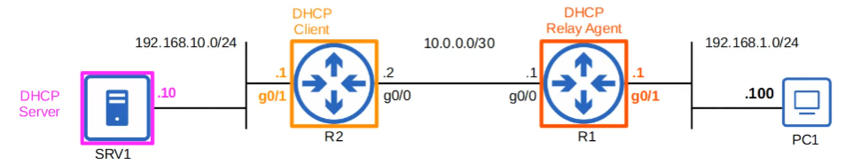
DHCP Replay Agent Configuration

1
2
3
4
5
6
7
8
9
10
11
12
13
14
15
//Configure the interface connected to the subnet of the client devices
R1(config)#interface g0/1

//Configure the IP address of the DHCP server as the 'helper' address (the actual address of the DHCP server) + ensure the relay agent has a route to the DHCP server
R1(config-if)#ip helper-address 192.168.10.10

R1(config-if)#do show ip interface g0/1
GigabitEthernet0/1 is up, line protocol is up
Internet address is 192.168.1.1/24
Broadcast address is 255.255.255.255
Address determined by non-volatile memory
MTU is 1500 bytes
Helper address is 192.168.10.10 // CHECK HERE

[output omitted]

DHCP Client (Use of DHCP to Configure the IP address of its interfaces); rare

1
2
3
4
5
6
7
8
9
10
11
12
//Choose the interface
R2(config)#interface g0/1

//Enable it. That's it.
R2(config-if)#ip address dhcp

R2(config-if)#do sh ip interface g0/1
GigabitEthernet0/1 is up, line protocol is up
Internet address is 192.168.10.1/24
Broadcast address is 255.255.255.255
Address determined by DHCP // HERE
[output omitted]

SNMPv2c Configurations (N)

1
2
3
4
5
6
7
8
9
10
11
12
13
14
15
//Optional Information 
R1(config)#snmp-server contact EMAIL/NUMBER/ETC
R1(config)#snmp-server location STRING

//Configure the SNMP community strings (passwords); ro = read only, rw = write only
R1(config)#snmp-server community Jeremy1 ro
R1(config)#snmp-server community Jeremy2 rw


//Specify address, NMS, version, and community (which dictates function)
R1(config)#snmp-server host 192.168.1.1 version 2c Jeremy1

//Specify traps; interface up or down traps, and config traps (notify)
R1(config)#snmp-server enable traps snmp linkdown linkup
R1(config)#snmp-server enable traps config

Syslog (N)

Enable logging on different systems

1
2
3
4
5
6
7
8
9
10
11
12
13
14
15
16
//configure logging into the console line (can use number or keyword (informational)) -- enables for gt 6
R1(config)#logging console SEVERITY

//configure logging to the vty lines
R1(config)#logging monitor SEVERITY
R1(config)#terminal monitor // enables Syslog messages in SSH or Telnet; required per connection

//configure logging to the buffer
R1(config)#logging buffered SIZE SEVERITY

//configure logging to an external server // both commands are same
R1(config)#logging SERVER-IP
OR
R1(config)#logging host SERVER-IP

R1(config)#logging trap SEVERITY // specifies the level of logging on external server

QOL Configurations

1
2
3
//prevents logs from truncating current typing
R1(config)#line console 0
R1(config-line)#logging sycnhronous

Service timestamps/Service sequence numbers

1
2
3
4
5
//Configure and enable the timestamp
R1(config)#service timestamps log [datetime / uptime]

//Enable sequence numbers
R1(config)#service sequence-numbers

SSH, Console Line, Telnet

Console Port Security - login

1
2
3
4
5
6
7
8
9
10
11
12
R1(config)#line console 0
R1(config-line)#password PASSWORD
R1(config-line)#login // required to tell user to enter the configured pwd
R1(config-line)#end
R1#exit

R1 con0 is now available
Press RETURN to get started.

User Access Verification
Password:
R1>

Console Port Security - login local

1
2
3
4
5
6
7
8
9
10
11
12
R1(config)#username NAME secret PASSWORD
R1(config)#line console 0
R1(config-line)#login local // requires device to require a user and pwd to login.
R1(config-line)#end
R1#exit

R1 con0 is now available
Press RETURN to get started.
User Access Verification
Username: NAME
Password:
R1>

Log the user out after X amount of inactivity

1
2
line con 0 
exec-timeout MINUTE SECOND

Layer 2 Switch - IP management

Assign an IP address to an SVI to allow remote connections to the CLI of the switch.
Recall switches do not have a routing table, and are not routing IP aware.

1
2
3
4
5
6
7
SW1(config)#interface vlan1
SW1(config-if)#ip address 192.168.1.253 255.255.255.0
SW1(config-if)#no shutdown

SW1(config-if)#exit

SW1(config)#ip default-gateway 192.168.1.254 // if not in the same LAN, send to a router

Telnet Configuration

1
2
3
4
5
6
7
8
9
10
11
12
13
14
15
16
17
18
19
20
//Required for telnet 
SW1(config)#enable secret PASSWORD
//Optional:
SW1(config)#username NAME secret PASSWORD

//Optional: configure ACL to limit which devices can connect to VTY lines
SW1(config)#access-list 1 permit host 192.168.2.1

//Telnet/SSH is configured on VTY lines; 16 lines available, so 16 users can be connected at once.
SW1(config)#line vty 0 15 //recommended so all lines have same config

//typical access configuration
SW1(config-line)#login local
SW1(config-line)#exec-timeout 50

//transport input ? -- specifies certain types of connections
SW1(config-line)#transport input telnet

//Optional: apply ACL to VTY lines only *note the access-class*
SW1(config-line)#access-class 1 in

SSH

Check SSH Support

1
2
3
4
5
// check ios image name for K9; NPE ISO images to countries with encryption restrictions
show version

// will tell you if it's supported here
show ip ssh

Generate RSA Keys

  • Must configure router host name and domain name.
    1
    2
    3
    4
    5
    6
    7
    //First, configure the domain name has RSA keys require the FQDN (host + domain) to generate
    SW1(config)#ip domain name EXAMPLE.COM

    //Generate key (will be SW1.EXAMPLE.COM), choose size of the key (2048)
    SW1(config)#crypto key generate rsa
    //cryto key generate rsa modulus LENGTH // alternative

Configure SSH

1
2
3
4
5
6
7
8
9
10
11
12
13
14
15
16
17
18
19
20
21
22
//Configure secret, username, and ACL (optional)
SW1(config)#enable secret PASSWORD
SW1(config)#username NAME secret PASSWORD2
SW1(config)#access-list 1 permit host IP-ADDRESS

//optional, recommended
SW1(config)#ip ssh version 2

//Used to access all 16 VTY lines
SW1(config)#line vty 0 15

//Only login local works (unlike Telnet)
SW1(config-line)#login local

//Configure timeout (optional)
SW1(config-line)#exec-timeout 50

//Limit the VTY line connection to SSH only, recommended.
SW1(config-line)#transport input ssh

//Apply ACL to all VTY lines (not input or output)
SW1(config-line)#access-class 1 in

Connect via SSH

1
2
3
4
5
ssh -l USERNAME IP-ADDRESS 

OR

ssh USERNAME@IP-ADDRESS

FTP and TFTP

TFTP: Upgrading Cisco ISO

1
2
3
4
5
6
7
8
9
10
11
12
13
14
15
16
17
18
19
//Check version, see crytographic support, etc
R1#show version

//view contents of flash
R1#show flash

//How to copy file from TFTP
R1#copy tftp: flash:
Address or name of remote host []? ENTER THE TFTP SERVER IP
Source filename []? ENTER NAME OF DESIRED FILE
Destination filename []? Enter name you want //(default: same name as in server)

R1(config)#boot system flash:NAME_OF_FILE // default - use first IOS file it finds
R1(config)#exit
R1#write memory // SAVE CONFIGURATION
R1#reload // restarts device
R1#show version // ensure version is correct, no issues
R1#delete flash:FILE_PATH // delete filepath

FTP: Copying Files

1
2
3
4
5
6
7
8
9
10
11
12
//Configure username and password R1 will use when connecting to FTP server
R1(config)#ip ftp username cisco

R1(config)#ip ftp password cisco

R1(config)#exit
R1#copy ftp: flash:
Address or name of remote host []? ENTER THE TFTP SERVER IP
Source filename []? ENTER NAME OF DESIRED FILE
Destination filename []? Enter name you want //(default: same name as in server)

//Rest is same as TFTP

NAT

Static Nat

Static NATs are a 1 to 1 mapping.

1
2
3
4
5
6
7
8
9
10
11
12
13
//Define the 'inside' interface(s) connected to the internal network
R1(config)#int g0/1
R1(config-if)#ip nat inside

//Define the 'outside' interface(s) connected to the external network.
R1(config-if)#int g0/0
R1(config-if)#ip nat outside
R1(config-if)#exit

//Configure the one-to-one IP address mappings; `ip nat inside sorce static INSIDE-LOCAL-IP INSIDE-GLOBAL-IP`
R1(config)#ip nat inside source static INSIDE-LOCAL-IP INSIDE-GLOBAL-IP
R1(config)#exit
1
2
3
4
5
6
7
8
//Show NAT translations
R1#show ip nat translations

//Clear all NAT translations; only clears dynamic, not static
R1#clear ip nat translations

//
R1#show ip nat statistics

Dynamic NAT Configuration

Configure Dynamic NAT

1
2
3
4
5
6
7
8
9
10
11
12
13
14
15
16
17
//Define the 'inside' interface(s) connected to the internal network
R1(config)#int g0/1
R1(config-if)#ip nat inside

//Define the 'outside' interface(s) connected to the external network.
R1(config-if)#int g0/0
R1(config-if)#ip nat outside
R1(config-if)#exit

//Define ACL for NAT; if not applied to an interface, it will NOT drop packets if no match.
R1(config)#access-list 1 permit IP-ADDRESS WILDCARD-MASK

//Define Pool of isnide global IP addresses
R1(config)#ip nat pool pool-name start-ip end-ip [prefix-length prefix-length | netmask subnet-mask]

//Map the ACL to the Pool
R1(config)#ip nat inside source list 1 pool POOL1

PAT (NAT Overload)

Configure PAT (almost same as Dynamic NAT with 1 difference: overload)

1
2
3
4
5
6
7
8
9
10
11
12
13
14
15
16
17
//Define the 'inside' interface(s) connected to the internal network
R1(config)#int g0/1
R1(config-if)#ip nat inside

//Define the 'outside' interface(s) connected to the external network.
R1(config-if)#int g0/0
R1(config-if)#ip nat outside
R1(config-if)#exit

//Define ACL for NAT; if not applied to an interface, it will NOT drop packets if no match.
R1(config)#access-list 1 permit IP-ADDRESS WILDCARD-MASK

//Define Pool of isnide global IP addresses
R1(config)#ip nat pool pool-name start-ip end-ip [prefix-length prefix-length | netmask subnet-mask]

//Map the ACL to the Pool
R1(config)#ip nat inside source list 1 pool POOL1 overload

More common way to configure PAT

1
2
3
4
5
6
7
8
9
10
11
12
13
14
15
//Define the 'inside' interface(s) connected to the internal network
R1(config)#int g0/1
R1(config-if)#ip nat inside

//Define the 'outside' interface(s) connected to the external network.
R1(config-if)#int g0/0
R1(config-if)#ip nat outside
R1(config-if)#exit

//Define ACL for NAT; if not applied to an interface, it will NOT drop packets if no match.
R1(config)#access-list 1 permit IP-ADDRESS WILDCARD-MASK

//Instead of specifying a pool and overload, just specify interface and overload
R1(config)#ip nat inside source list 1 interface INTERFACE-ID overload

QoS | PoE and VoIP


IP Phones / Voice VLAN to Enable

1
2
3
4
5
6
7
8
9
10
SW1(config)#int g0/0
SW1(config-if)#switchport mode access
// Data traffic recieved by g0/0 will remian untagged. SW1 will use CDP to tell PH1 to tag PH1's traffic in VLAN 11
SW1(config-if)#switchport access vlan 10 // data VLAN
SW1(config-if)#switchport voice vlan 11 // voice VLAN

// note* that g0/0 is still an access port; even if it contians 2 vlans
SW1#show int g0/0 switchport // can use to verify
SW1#show interfaces trunk // will not see g0/0
SW1#show interfaces g0/0 trunk // status will be not-trunking

Power Policing for PSE to PD Devices

1
2
3
4
5
6
7
8
//default settings: disable the port and send a Syslog if a PD draws too much power
SW1#power inline police

//same as `power inline police` ; interface will be put in error-disabled state, and can be re-enabled with shutdown/no shutdown
SW1#power incline police action err-disable

//command does not shutdown interface; just sends a syslog and restarts interface
SW1#power inline police acton log

QoS (N)

Identify the special type of traffic for QoS.

1
2
3
4
5
6
7
8
9
10
11
12
13
14
15
16
17
18
19
20
21
22
23
24
25
26
27
//Create a class map 
R1(config)#class-map HTTP_MAP
R1(config-cmap)#match protocol ?
arp IP ARP
bgp Border Gateway Protocol
cdp Cisco Discovery Protocol
dhcp Dynamic Host Configuration
dns Domain Name Server lookup
eigrp Enhanced Interior Gateway Routing Protocol
ftp File Transfer Protocol
gre Generic Routing Encapsulation
h323 H323 Protocol
http Hypertext Transfer Protocol
https Secure Hypertext Transfer Protocol
icmp ICMP
ip IP
ipsec IP Security Protocol (ESP/AH)
ipv6 IPV6
ntp Network Time Protocol
ospf Open Shortest Path First
pop3 Post Office Protocol
rip Routing Information Protocol
rtp Real Time Protocol
skinny Skinny Call Control Protocol
smtp Simple Mail Transfer Protocol

R1(config-cmap)#match protocol http

Show commands

1
2
3
4
5
6
7
8
//Class maps currently are "match-all" because we defined our our type. We can use 'match-all' or 'match-any' as needed
R1(config)#do sh run | section class-map
class-map match-all HTTPS_MAP
match protocol https
class-map match-all HTTP_MAP
match protocol http
class-map match-all ICMP_MAP
match protocol icmp

Specify the treatment for traffic

1
2
3
4
5
6
7
8
9
10
11
12
13
14
15
16
17
18
19
20
21
22
23
24
25
26
27
28
29
30
31
32
33
34
35
36
37
38
39
40
41
42
43
44
45
46
47
48
49
50
51
52
53
54
//policy-map NAMED is applied to an interface 
R1(config)#policy-map ?
WORD policy-map name
type type of the policy-map
R1(config)#policy-map G0/0/0_OUT
R1(config-pmap)#?
class policy criteria
exit Exit from policy-map configuration mode
no Negate or set default values of a command

//Then identify class-map that we configured
R1(config-pmap)#class HTTPS_MAP
R1(config-pmap-c)#?
bandwidth Bandwidth
exit Exit from class action configuration mode
no Negate or set default values of a command
priority Strict Scheduling Priority for this Class
queue-limit Queue Max Threshold for Tail Drop
random-detect Enable Random Early Detection as drop policy
service-policy Configure Flow Next
set Set QoS values
shape Traffic Shaping
R1(config-pmap-c)#set ip dscp ?
<0-63> Differentiated services codepoint value
af11 Match packets with AF11 dscp (001010)
af12 Match packets with AF12 dscp (001100)
af13 Match packets with AF13 dscp (001110)
af21 Match packets with AF21 dscp (010010)
af22 Match packets with AF22 dscp (010100)
af23 Match packets with AF23 dscp (010110)
af31 Match packets with AF31 dscp (011010)
af32 Match packets with AF32 dscp (011100)
af33 Match packets with AF33 dscp (011110)
af41 Match packets with AF41 dscp (100010)
af42 Match packets with AF42 dscp (100100)
af43 Match packets with AF43 dscp (100110)
cs1 Match packets with CS1(precedence 1) dscp (001000)
cs2 Match packets with CS2(precedence 2) dscp (010000)
cs3 Match packets with CS3(precedence 3) dscp (011000)
cs4 Match packets with CS4(precedence 4) dscp (100000)
cs5 Match packets with CS5(precedence 5) dscp (101000)
cs6 Match packets with CS6(precedence 6) dscp (110000)
cs7 Match packets with CS7(precedence 7) dscp (111000)
default Match packets with default dscp (000000)
ef Match packets with EF dscp (101110)

//Marks any HTTPS packet with DSCP with AF31
R1(config-pmap-c)#set ip dscp af31
R1(config-pmap-c)#priority ?
<8-2000000> Kilo Bits per second
percent % of total bandwidth

//Sets our HTTPS traffic priority queue of at least 10% during times of congestion
R1(config-pmap-c)#priority percent 10

Port Security: Layer 2 (DHCP snooping, dynamic ARP inspection, port)

Port Security

Enabling Port Security

1
2
3
4
5
6
7
8
9
10
11
12
13
14
15
16
17
18
19
20
//By default, most SW interfaces are 'dynamic auto'; need to configure to `mode {access | trunk}`
SW1(config)#int g0/1
SW1(config-if)#switchport mode {access | trunk}
//Now port security can be enabled
SW1(config-if)#switchport port-security // first MAC address that interfacts with g0/1 is saved

//Show
SW1#show port-security int g0/1
Port Security : Enabled
Port Status : Secure-up
Violation Mode : Shutdown // default behavior
Aging Time : 0 mins
Aging Type : Absolute
SecureStatic Address Aging : Disabled
Maximum MAC Addresses : 1
Total MAC Addresses : 1
Configured MAC Addresses : 0
Sticky MAC Addresses : 0
Last Source Address:Vlan : 0001.9684.E019:1
Security Violation Count : 0

Re-enabling a Secure-down status / err-disabled

1
2
3
SW1(config)#int g0/1
SW1(config-if)#shutdown
SW1(config-if)#no shutdown

Allowing automatic re-enable of Err-Disabled State (ErrDisable Recovery)

1
2
3
4
5
6
7
8
9
10
11
12
13
14
15
16
17
18
19
20
21
22
23
24
25
26
27
SW#show errdisable recovery
ErrDisable Reason Timer Status
----------------- ------------
arp-inspection Disabled
bpduguard Disabled
dtrm Disabled
fc Disabled
hSRP Disabled
lacp Disabled
mac-address Disabled
ndp-inspection Disabled
pagp Disabled
port-security Disabled
psc Disabled
pvstn Disabled
qos Disabled
rootguard Disabled
secopt Disabled
spanning-tree Disabled
udld Disabled
unk-l2-flood Disabled
vlan Disabled
[...]

//Enable auto-recovery, but ensure to remove the device causing the issue first.
SW1(config)#errdisable recovery cause psecure-violation
SW1(config)#errdisable recovery interval 180

Violation Modes for Unauthorized MAC address (Port-Security)

  1. Shutdown: err-disables interface; 1 syslog
  2. Restrict: discards all traffic from unauthorized MAC address; syslogs per traffic
  3. Protect: discards all traffic from unauthorized MAC address; no syslog
    1
    2
    3
    4
    5
    SW1(config-if)#switchport port-security
    //manually configure MAC address
    SW1(config-if)#switchport port-security mac-address MAC-ADDRESS
    //Enable restrict mode
    SW1(config-if)#switchport port-security violation {shutdown | restrict | protect}

Secure MAC Address Aging

  • By default, secure MAC addresses will not age out: (Aging Time: 0 minutes);
  • Absolute: MAC address is removed after timer expires, but can be immediately relearned on a new frame
  • Inactivity: aging timer is reset every time a frame from the source MAC address is received
    1
    SW1(config-if)#switchport port-security aging type {absolute | inactivity}

Static secure MAC addresses can be made to age out as follows:

1
SW1(config-if)#switchport port-security aging static

Show command

1
SW1#show port-security

Sticky Secure MAC Addresses

1
2
3
4
5
6
//Dynamically learned secure MAC addresses will be converted to 'sticky secure' and added to the running-config
//Think of it as a way to configure secure MAC addresses without manually configuring them
SW1(config-if)#switchport port-security mac-address sticky
//sticky secure will never age out, make sure to save running-config

SW1(config)#show mac address-table secure

DHCP Snooping

Messages from a DHCP server (OFFER, ACK, NAK) are discarded.

In untrusted interfaces, messages from a DHCP client (DISCOVER or REQUEST messages) are forwarded only if the source MAC address in the Ethernet frame matches the CHADDR field within the DHCP message. (Source MAC Address (Ethernet) === CHADDR)
Messages from a DHCP client (RELEASE or DECLINE messages) are forwarded only if the source IP address in the packet matches the entry in the DHCP Snooping Binding Table for the receiving interface.

Enable DHCP Snooping

1
2
3
4
5
6
7
8
9
10
//Enable DHCP Snooping globally; 
SW2(config)#ip dhcp snooping

//MUST specify the VLAN for DHCP snooping
SW2(config)#ip dhcp snooping vlan1
SW2(config)#no ip dhcp snooping information option

//specify trusted ports; by default all ports are untrusted
SW2(config)#int g0/0
SW1(config-if)#ip dhcp snooping trust
1
2
3
4
5
6
7
8
9
10
//Enable DHCP Snooping globally; 
SW1(config)#ip dhcp snooping

//MUST specify the VLAN for DHCP snooping
SW1(config)#ip dhcp snooping vlan1
SW1(config)#no ip dhcp snooping information option

//specify trusted ports; by default all ports are untrusted
SW1(config)#int g0/0
SW1(config-if)#ip dhcp snooping trusted

What is no ip dhcp information option?

  • Option 82 is reserved for DHCP delay agents.
  • By default, Cisco switches and routers will drop option 82 on untrusted ports (with DHCP Snooping). A switch’s default settings will add “Option 82”, so the following switch will drop the DISCOVER + OPTION 82 packet (if settings are default).
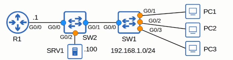
  • The default options work well if the the switch is a layer 3 switch acting as a DHCP relay agent, which is not the case in the diagram.

Show command
CLIENT: RELEASE/DECLINE messages will be checked with the DHCP Snooping Bind table; IP address and interface ID needs to match

1
2
3
4
5
6
SW1#show ip dhcp snooping binding
MacAddress IpAddress Lease(sec) Type VLAN Interface
------------------ --------------- ---------- ------------- ---- -----------------
00:01:64:32:B9:22 192.168.1.10 86400 dhcp-snooping 1 FastEthernet0/1
00:60:70:DB:6A:23 192.168.1.11 86400 dhcp-snooping 1 FastEthernet0/2
00:0A:41:A6:B6:0E 192.168.1.12 86400 dhcp-snooping 1 FastEthernet0/3

DHCP Snooping Rate - Limiting

1
2
3
4
5
6
7
SW1(config)#int range g0/1 - 3

//limits interface rate to 1 per second
SW1(config-if-range)#ip dhcp snooping limit rate X-PER-SEC

//enable errdisable recovery for rate-limiting ; default is 5 minute (300 sec)
SW1(config)#errdisable recovery cause dhcp-rate-limit

Dynamic ARP Inspection (DAI)

Enable DAI

1
2
3
4
5
6
//Enable DAI on specific VLAN(s)
SW2(config)#ip arp inspection vlan VLAN-ID

//Configure trusted ports for ARP
SW2(config)#int range g0/0 - 1
SW2(config-if-range)#ip arp inspection trust
1
2
3
4
5
6
//Same configurations for SW1, with respective trusted ports
SW1(config)#ip arp inspection vlan VLAN-ID

//Configure trusted ports for ARP
SW1(config)#int range g0/0
SW1(config-if-range)#ip arp inspection trust

View Trust State, Rate, and Burst Intervals of each interface, configure errdisable actions

1
2
3
4
5
6
7
8
9
10
11
SW1#show ip arp inspection interfaces

//rate-limiting (15/pps) is enabled on untrusted ports by default (unlike DHCP snooping, rate-limiting is diabled by default)
//DAI allows "burst interval" (e.g., x packets per y seconds VS a simple x packets per sec)
SW1(config)#int range g0/0 - 2
SW1(config-if-range)#ip arp inspection limit rate 25 burst interval 2 // 25 packets per 2 seconds (optional: burst interval; default: 1)


//Interfaces that exceed input rate limit are err-disabled. Re-enable as follows:
1. shutdown => no shutdown //OR
SW1(config)#errdisable recovery cause arp-inspection

DAI Optional Checks
Default: DAI checks sender MAC and and IP addresses for matching entry in DHCP snooping binding table

1
2
3
4
5
6
7
8
//Additional Checks for DAI
SW1(config)#ip arp inspection validate ?
dst-mac
ip
src-mac

//Enable all 3 validations (one will override another if not done this way)
SW1(config)#ip arp inspection validate ip src-mac dst-mac

ARP ACLs (N)

1
2
3
4
5
6
7
//Static addresses do not have an entry in the dhcp snooping binding table. 
//ACL must be configured for end-hosts like SRV1.
SW2(config)#arp access-list ARP-ACL-1
SW2(config-arp-nacl)#permit ip host 192.168.1.100 mac host 0c29.2f1e.7700
//Apply the ACL; note* static ACL is not configured here; so will also check the snooping table b/c no implict deny
SW2(config)#ip arp inspection filter ARP-ACL-1 vlan VLAN-ID

HSRP

1
2
3
4
5
6
7
8
9
10
11
12
13
14
15
16
17
18
19
20
21
22
23
24
25
26
27
28
29
30
31
32
33
34
35
36
37
38
39
40
41
42
43
44
45
//Enter a VLAN first
SW1(config)#int vlan VLAN-ID

//Configure HSRP to version 2
DSW1(config-if)#standby ?
<0-4095> group number
ip Enable HSRP and set the virtual IP address
ipv6 Enable HSRP IPv6
preempt Overthrow lower priority Active routers
priority Priority level
timers Hello and hold timers
track Priority Tracking
version HSRP version
DSW1(config-if)#standby version 2

//Create a group (prefer to match VLAN, but not required), and assign a default gateway (??); think it's virtual IP
DSW1(config-if)#standby ?
<0-4095> group number
ip Enable HSRP and set the virtual IP address
ipv6 Enable HSRP IPv6
preempt Overthrow lower priority Active routers
priority Priority level
timers Hello and hold timers
track Priority Tracking
version HSRP version
DSW1(config-if)#standby version 2
DSW1(config-if)#standby 10 ?
ip Enable HSRP and set the virtual IP address
ipv6 Enable HSRP IPv6
preempt Overthrow lower priority Active routers
priority Priority level
timers Hello and hold timers
track Priority Tracking
DSW1(config-if)#standby 10 ip ?
A.B.C.D Virtual IP address
<cr>
DSW1(config-if)#standby 10 ip 10.0.10.254

//Increase priority from default of 100 ; lower priority gets elected (in contrast, OSPF, higher is elected haha)
DSW1(config-if)#standby 10 priority ?
<0-255> Priority value
DSW1(config-if)#standby 10 priority 105

//Enable preempt
DSW1(config-if)#standby 10 preempt

VRF-lite (N)

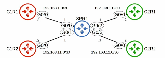
Without the use of VRF, two interfaces on the same router cannot be in the same subnet

1
2
3
4
5
6
7
8
9
10
11
12
13
14
SPR1(config)# interface g0/0
SPR1(config-if)# ip address 192.168.1.1 255.255.255.252
SPR1(config-if)# no shutdown

SPR1(config-if)# interface g0/1
SPR1(config-if)# ip address 192.168.11.1 255.255.255.252
SPR1(config-if)# no shutdown

SPR1(config-if)# interface g0/2
SPR1(config-if)# ip address 192.168.1.1 255.255.255.252
% 192.168.1.0 overlaps with GigabitEthernet0/0

SPR1(config-if)# ip address 192.168.1.2 255.255.255.252
% 192.168.1.0 overlaps with GigabitEthernet0/0

With VRF

Create VRF

  1. Create VRFS: ip vrf NAME
  2. Assign interfaces to VRFs: ip vrf forwarding NAME
    1
    2
    3
    4
    5
    6
    7
    8
    9
    10
    11
    12
    13
    14
    15
    16
    17
    18
    19
    20
    21
    22
    23
    24
    25
    SPR1(config)#ip vrf CUSTOMER1
    SPR1(config-vrf)#ip vrf CUSTOMER2
    SPR1(config-vrf)# do show ip vrf

    SPR1(config-vrf)# interface g0/0
    SPR1(config-if)# ip vrf forwarding CUSTOMERS
    //VRFs remove IP-addresses already configured; so re-configure as needed
    % Interface GigabitEthernet0/0 IPv4 disabled and address(es) removed due to enabling VRF CUSTOMER1
    SPR1(config-if)# ip address 192.168.1.1 255.255.255.252

    SPR1(config-if)# interface g0/1
    SPR1(config-if)# ip vrf forwarding CUSTOMER1
    % Interface GigabitEthernet0/1 IPv4 disabled and address(es) removed due to enabling VRF CUSTOMER1
    SPR1(config-if)# ip address 192.168.11.1 255.255.255.252

    //WORKS NOW--even if in the same subnet
    SPR1(config-if)# interface g0/2
    SPR1(config-if)# ip vrf forwarding CUSTOMER2
    SPR1(config-if)# ip address 192.168.1.1 255.255.255.252
    SPR1(config-if)# no shutdown
    SPR1(config-if)# interface g0/3
    SPR1(config-if)# ip vrf forwarding CUSTOMER2

    SPR1(config-if)# ip address 192.168.12.1 255.255.255.252
    SPR1(config-if)# no shutdown

Show command

Global routing table will not show VRF; fix as follows:

1
show ip route vrf NAME

Ping Commands
Normal pings follow the global routing table; fix as follows:

1
ping vrf NAME IP-ADDRESS